Rotational connector device

a technology of rotating connectors and connectors, which is applied in the direction of insulating conductors, cables, and relatively moving parts, can solve the problems of flat cable buckles and heavy weight of rotating connector devices, and achieve the effect of suppressing flat cable buckling and light weigh

Inactive Publication Date: 2013-01-17
VALEO JAPAN CO LTD
View PDF3 Cites 2 Cited by
  • Summary
  • Abstract
  • Description
  • Claims
  • Application Information

AI Technical Summary

Benefits of technology

[0009]Accordingly, the present invention is made in view of the above described problems, and the present invention has an object to provide a rotational connector device which is light-weighed and in which a route of a flat cable is appropriately regulated to prevent buckling of the flat cable.
[0016]According to the aspect of the present invention, the route of the flat cable is regulated by the first guide portion, the first guide portion is not formed in a framed shape in which the entire circumference is closed, but comprises the inner guide rib and the outer guide rib separated, each rib having the curved surface, to remove the intermediate section therebetween, and also in the annular plate portion, a region sandwiched by the inner guide rib and the outer guide rib forms a lightening hole. Therefore the rigidity is maintained by each curved surface of both the guide ribs, the spacer is made light in weight, and the sliding resistance to the flat cable at rotor rotating is reduced to effectively suppress the buckling of the flat cable.

Problems solved by technology

However, the conventional rotational connector device is heavy since the spacer is structured such that many frame-shaped guide walls are provided to rise on the annular plate portion.
As a result, because of a large sliding resistance to the flat cable generated at rotor rotating, there is a possibility that the flat cable buckles at the time the flat cable pushes a side wall of the guide wall.
However, the rotational connector device disclosed in Japanese Patent Issue No. 4355229 can not set such an indicator.

Method used


Image

  • Rotational connector device
  • Rotational connector device
  • Rotational connector device

Examples


Embodiment Construction

[0023]Hereinafter, an embodiment in the present invention will be explained with reference to the accompanying drawings.

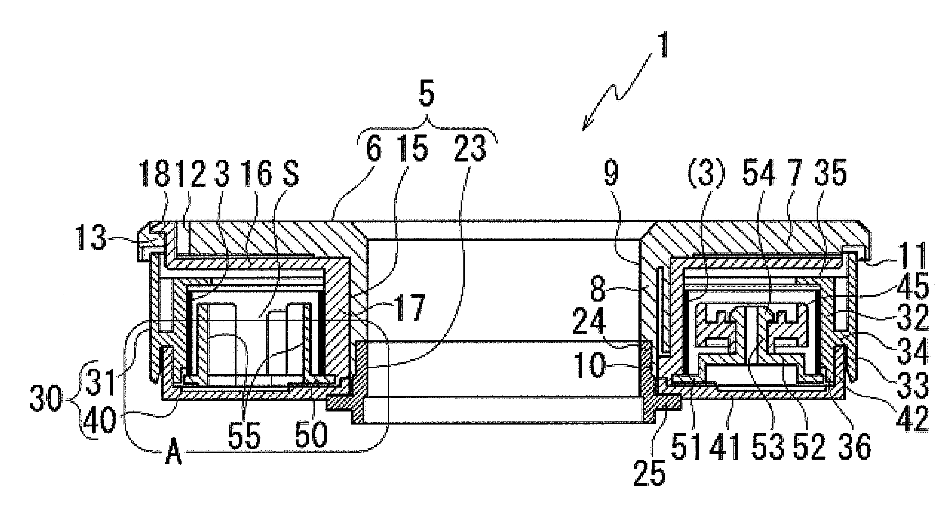
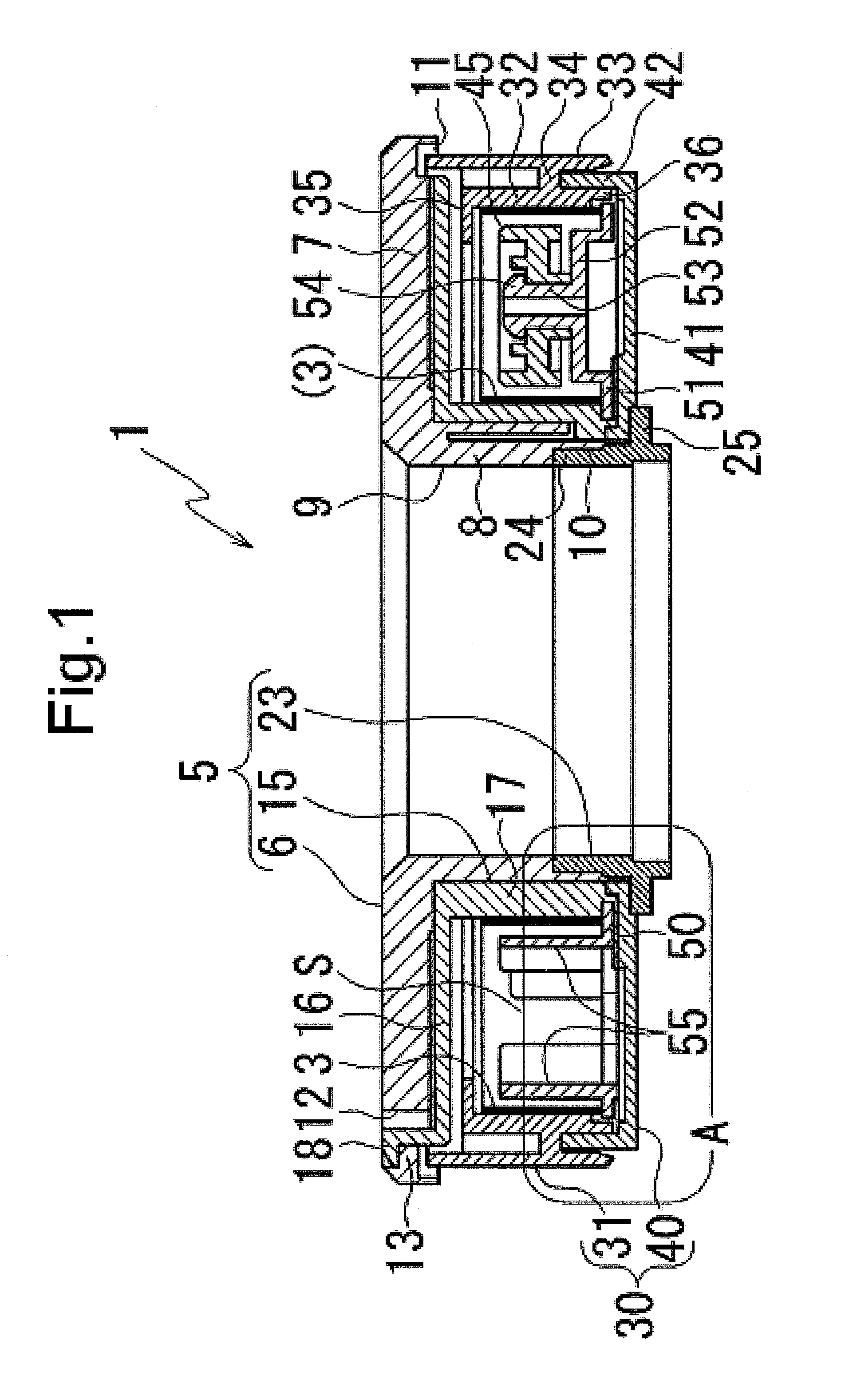
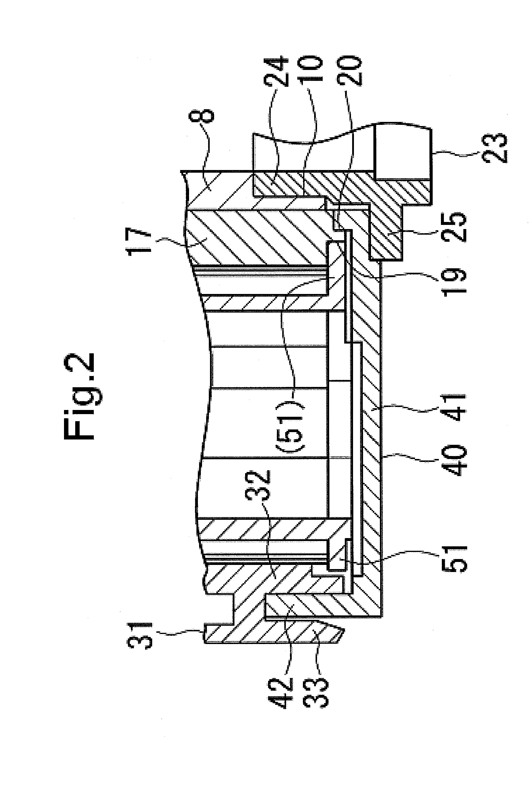
[0024]FIG. 1 is a cross section showing a rotational connector device according to an embodiment, and FIG. 2 is an enlarged view of A portion in FIG. 1. A rotational connector device 1 comprises a rotor 5, a stator 30, and a flat cable 3 and a spacer 50 arranged between the rotor 5 and the stator 30. The rotor 5 comprises a rotor body 6, a liner 15, and a rotor attachment 23, each being made of plastic. The rotor body 6 includes a disc portion 7, and a cylindrical portion 8 axially extending from the center of the disc portion 7 and having a through hole 9 therein. An inner diameter of the cylindrical portion 8 in a predetermined range from a front end thereof forms an enlarged diameter portion 10 larger than that of the upper section. A ring-shaped groove 11 is formed in an inner side just proximal to an outer peripheral edge on the backside of the disc portion 7....


PUM


Abstract

A spacer arranged in an annular space between a rotor and a stator for supporting a roller reversing a winding direction of a flat cable is made of plastic having high lubricating properties. First guide portions on an annular plate portion are spaced by equal intervals from each other. The first guide portion includes an inner guide rib having a semicircle cross section projecting inward, an outer guide rib having a semicircle cross section projecting outward, and a tension wall connecting the inner guide rib and the outer guide rib. A second guide portion is provided between the first guide portions, and includes three parallel plate ribs extending from an inner peripheral side to an outer peripheral side of the annular plate portion, and circumferential connecting walls connecting the three parallel plate ribs.

Description

CROSS-REFERENCE TO RELATED APPLICATION[0001]This application claims priority under 35 USC 119 from Japanese Patent Application No. 154062 / 2011 filed on Jul. 12, 2011, the disclosure of which is incorporated by reference herein.BACKGROUND OF THE INVENTION[0002]1. Field of the Invention[0003]The present invention relates to a rotational connector device which is used in a relatively rotational component to perform an electrical connection for control of an air bag device incorporated in a steering device for an automobile or control of an audio device or a constant speed traveling device by a switch button provided on a steering wheel for an automobile.[0004]2. Description of the Related Art[0005]An example of this kind of rotational connector device includes a device where an annular space is formed between a rotor coupled to a rotating steering shaft and a stator coupled to a vehicle fixed side and a flat cable a winding direction of which is reversed in the middle is accommodated i...

Claims


Application Information

Patent Timeline
Patent Type & Authority Applications(United States)
IPC IPC(8): H01R35/04
CPCB60R16/027H01R35/04B62D1/04H01R35/025H02G11/00
Inventor SAKURAI, JUNICHISERIZAWA, YASUMASA
Owner VALEO JAPAN CO LTD
Why Eureka
Try Eureka