Projector and unit for projector

a projector and unit technology, applied in the field of projectors, can solve the problems of complex work for connecting various cables included in the optional unit to the projector, complicating the removal of the panel, and inability to perform smoothly, so as to improve the ease of work and simplify the connection work of the unit

Inactive Publication Date: 2011-09-01
NEC DISPLAY SOLUTIONS LTD
View PDF8 Cites 3 Cited by
  • Summary
  • Abstract
  • Description
  • Claims
  • Application Information

AI Technical Summary

Benefits of technology

[0012]According to the present invention, by removing only the side face member from the case and guiding the unit by the guide member to move toward the connector of the substrate, the electrical connection between the terminal of the unit and the connector of the substrate is completed, enabling the unit to function. Thus, according to the present invention, when the unit is mounted on the projector, complex work for connecting the cable of the unit to the substrate can be made unnecessary, and work for removing a plurality of outer case members constituting the case can be made unnecessary. As a result, connection work of the unit can be simplified, improving the ease with which the work can be carried out.

Problems solved by technology

As a result, when the optional unit is mounted on the projector, work for connecting various cables included in the optional unit to the projector is complex.
However, the work for inserting the various cables included in the optional unit into the connectors of the substrates to electrically connect the cables is a task that is difficult to implement when carried out only from one side face from which the side panel has been removed, and hence the work cannot be performed smoothly.
Thus, other panels such as a top panel and a front panel must also be removed from the case of the projector, complicating the panel removal work.
In addition, even in the state of the top panel and the front panel have been removed, at those locations where cables have been inserted into the connectors, the surrounding space in the projector is relatively narrow, and therefore, it is difficult to carry out the task of inserting cables into the connectors.

Method used


Image

  • Projector and unit for projector
  • Projector and unit for projector
  • Projector and unit for projector

Examples


Embodiment Construction

[0046]Hereinafter, specific embodiments of the present invention are described with reference to the drawings.

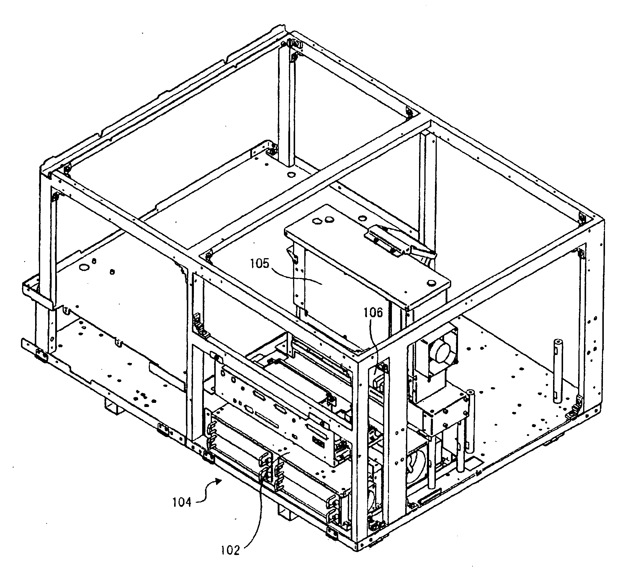
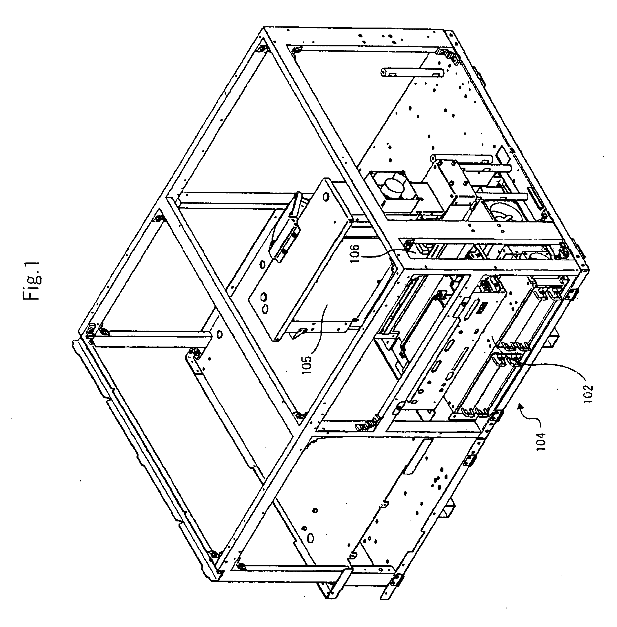
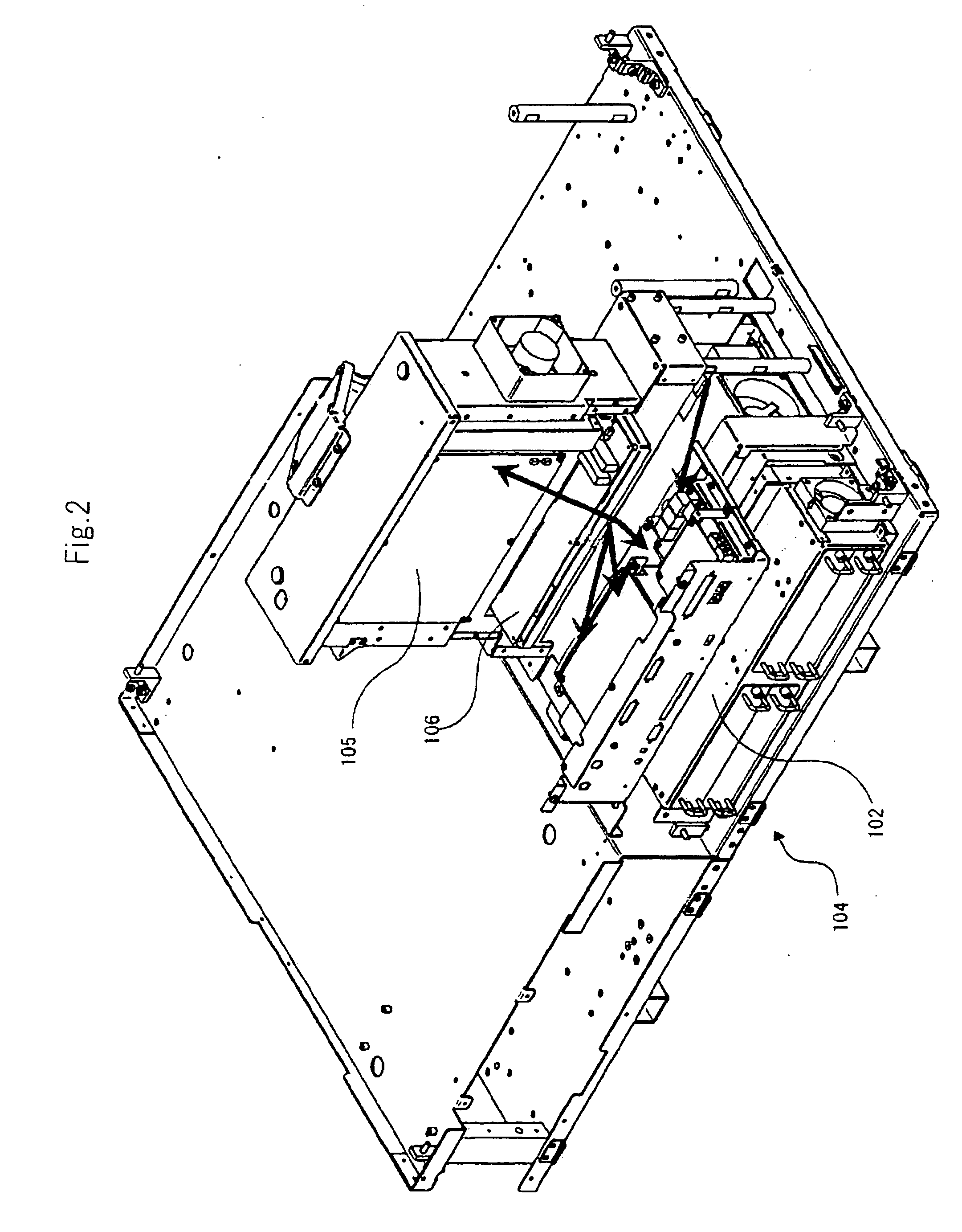
[0047]As shown in FIGS. 3 to 8, projector 1 according to an embodiment includes mounting unit 4 for selectively mounting optional unit 2 to extend functions installed beforehand. First, optional unit 2 mounted on projector 1 according to the embodiment is described referring to the drawings.

[0048]As shown in FIG. 9, according to the embodiment, optional unit 2 includes, as extension function section 5, a plurality of extension slots on which, for example, extension boards are mounted, a fan for cooling the extension boards mounted on the extension slots, and a control circuit unit for controlling the extension boards and the fan. Optional unit 2 also includes connection substrate 7 electrically connected to the control circuit unit constituting extension function section 5 via cable 6.

[0049]At one end of connection substrate 7, terminal 7a is disposed to be electrically conn...


PUM


Abstract

A projector includes: a mounting unit for mounting optional unit (2) having an extension function section, connection substrate (7), and cable (6) for electrically connecting the extension function section and connection substrate (7); mother substrate (31) having connector (31a) to which terminal (7a) is electrically connected; Z-shaped guide metal fitting (40) located on the mounting unit and configured to movably guide terminal (7a) to connector (31a); and a case having mother substrate (31) located therein. One side face of the case has an opening for inserting/removing optional unit (2) into/from the case, and a side panel for covering the opening being removably located in the opening. When optional unit (2) is inserted into the case from the opening, connection substrate (7) is guided by Z-shaped guide metal filling (40), and optional unit (2) functions when terminal (7a) is electrically connected to connector (31a).

Description

TECHNICAL FIELD[0001]The present invention relates to a projector for projecting an image on a projection surface such as a screen, and a unit for a projector, which is mounted on the projector.BACKGROUND ART[0002]A projector configured to selectively mount, when needed, an optional board (extension board) that is a circuit board having various extension functions to extend functions provided beforehand in the projector is disclosed in, for example, JP2004-264759A. For such a projector, there is known a configuration that includes a mounting unit for selectively mounting an optional unit having various extension function sections.[0003]As the optional unit of this type, for example, there are a wireless LAN (Local Area Network) unit, a RGB (red, green, and blue) signal distribution unit, and an adaptor unit including an extension slot to mount the extension board, each of which includes a plurality of cables electrically connected to substrates located in the projector.[0004]As show...

Claims


Application Information

Patent Timeline
Patent Type & Authority Applications(United States)
IPC IPC(8): H05K5/00
CPCG03B21/14G03B21/145
Inventor TAKEDA, MIKIYA
Owner NEC DISPLAY SOLUTIONS LTD
Why Eureka
Try Eureka