
Camera module with Anti-shake device

Inactive Publication Date: 2011-09-01
SAMSUNG ELECTRO MECHANICS CO LTD
View PDF2 Cites 38 Cited by
  • Summary
  • Abstract
  • Description
  • Claims
  • Application Information

AI Technical Summary

Benefits of technology

[0016]According to the present invention, a camera module equipped with a vibration compensation mechanism is provided. That is, the present invention implements a camera module equipped with a vibration compensation mechanism that can prevent the focus of a camera from being blurred by the vibration of the hands which hold the camera during its use, and the present invention provides a camera module equipped with a vibration compensation mechanism, which enables the thickness of a camera to be reduced because the vibration compensation mechanism is provided beside a lens unit and which minimizes the amount of current required to operate an auto-focus actuator unit because the weight supported by the auto-focus actuator unit is reduced.

Problems solved by technology

However, since vibration compensation mechanisms fitted to digital cameras are relatively large, new research needs to be carried out on vibration compensation mechanisms to be applied to cameras for mobile devices.
Although a stand for preventing a camera from vibrating is sometimes used to mitigate the above-described problem, the camera stand inconveniences general users because it is large-sized, is heavy, and has a complicated method of use.
When a user attempts to capture an image without using the camera stand because of the above inconvenience, the focus of the camera module is blurred by the vibration of the user's hands, and therefore a reduction in the quality of a captured image occurs.
The above problems do not only meet consumers' demands for the convenient use of cameras and high image quality, but also incur expenses resulting from the disposal of low-quality photos.

Method used


Image

  • Camera module with Anti-shake device
  • Camera module with Anti-shake device
  • Camera module with Anti-shake device

Examples


Embodiment Construction

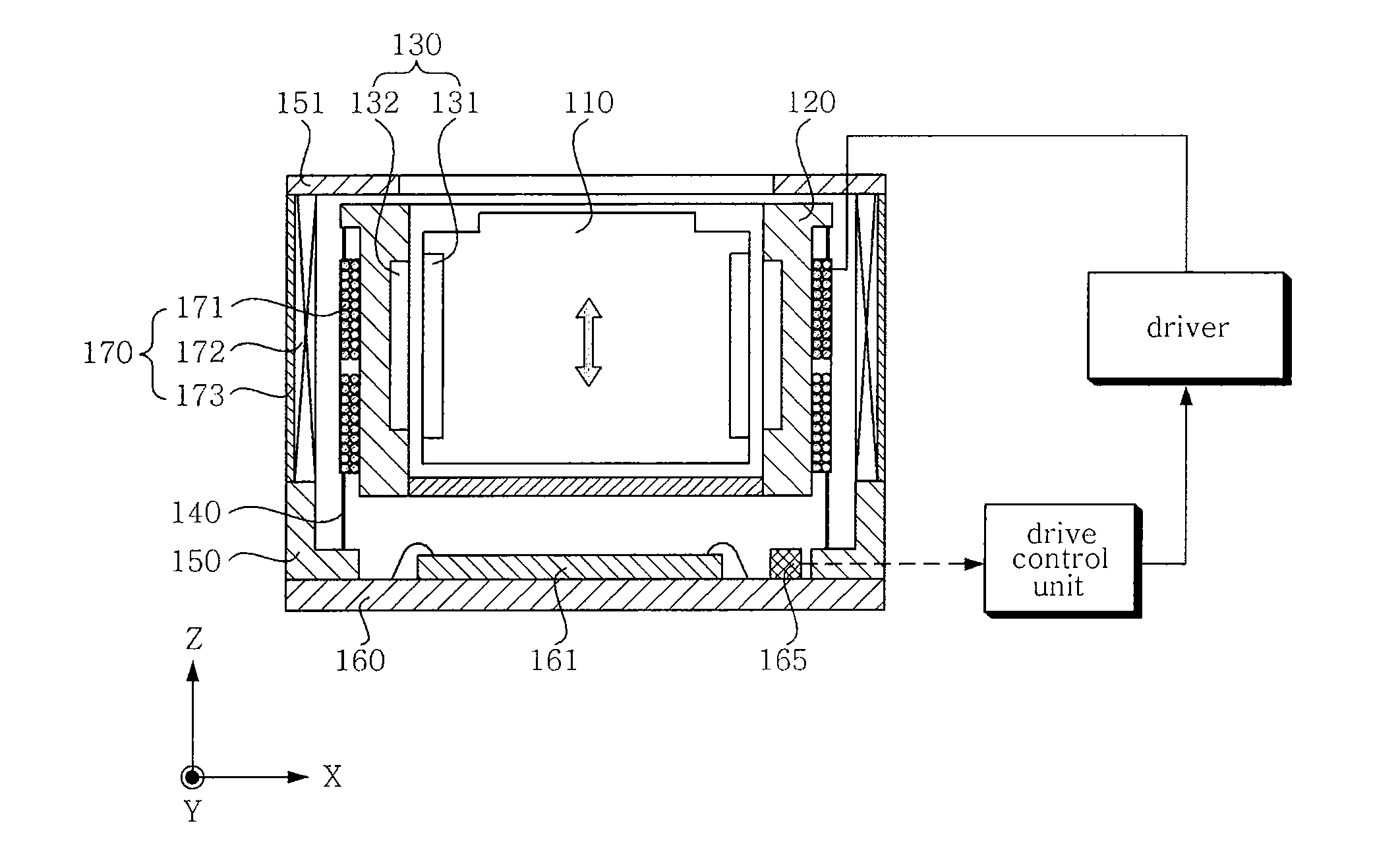
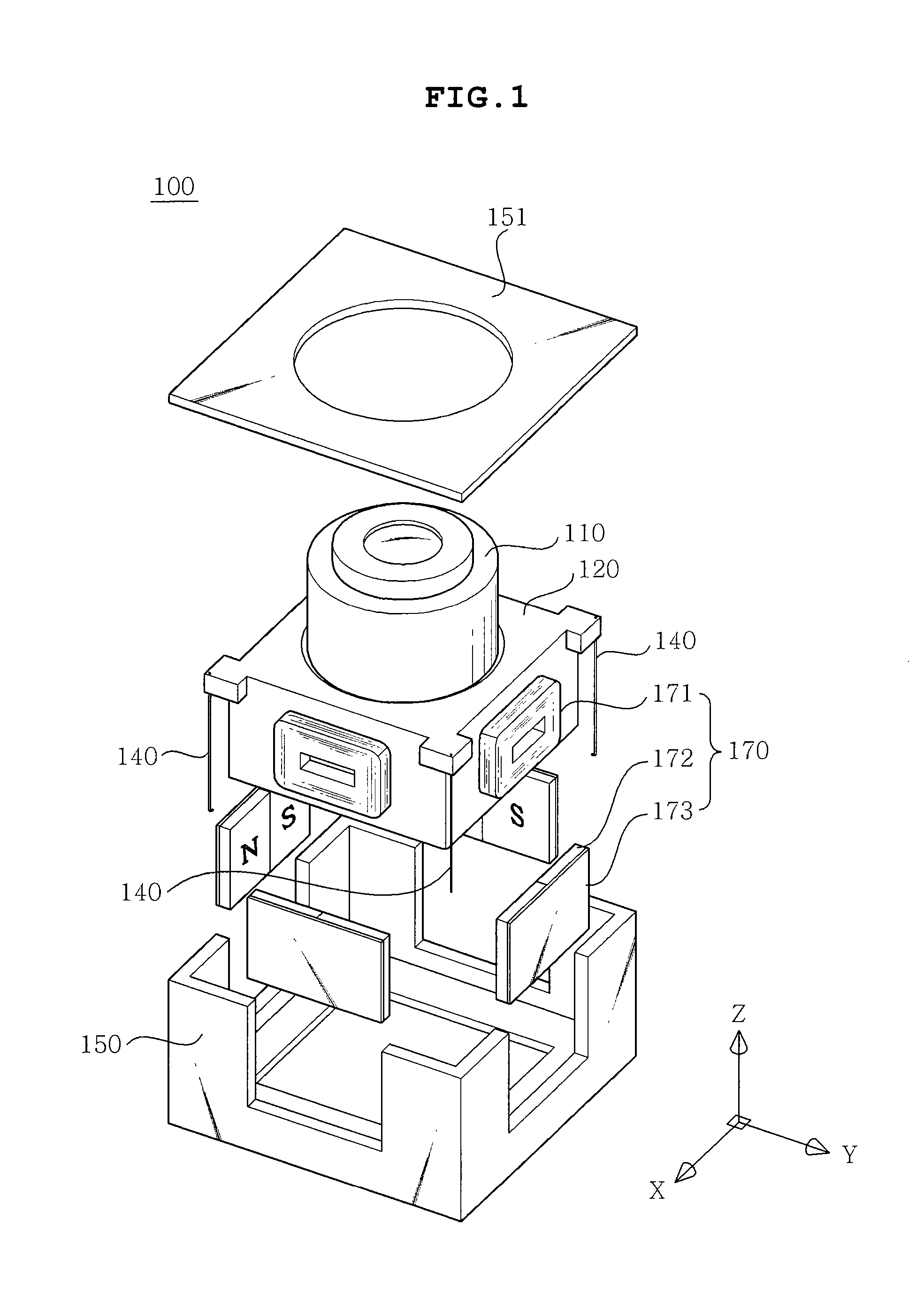
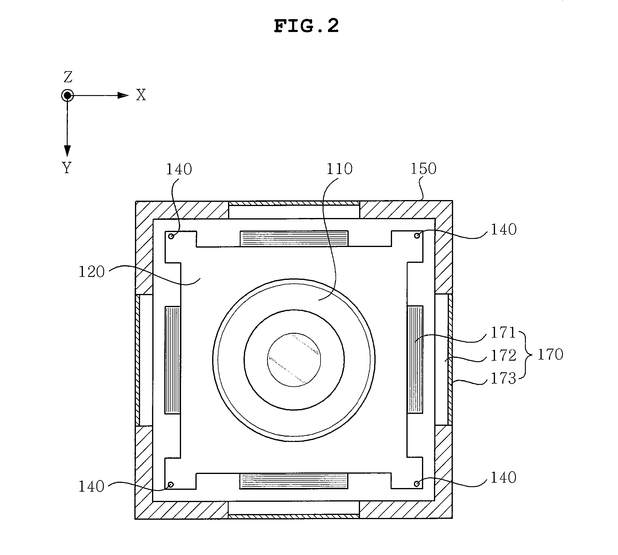
[0023]A camera module 100 equipped with a vibration compensation mechanism according to an embodiment of the present invention will be described in detail below with reference to the accompanying drawings.

[0024]As shown in FIGS. 1 to 3, the camera module 100 equipped with a vibration compensation mechanism according to an embodiment of the present invention includes a lens unit 110, a housing 120, an auto-focus actuator unit 130, a suspension member 140, a case 150, a circuit board 160, and a compensation actuator 170.

[0025]The lens unit 110 includes a plurality of lenses which are used to change an image of a subject at a specific magnification.

[0026]The housing 120 accommodates the lens unit 110, allows the lens unit 110 to move in the direction of an optical axis, and includes an auto-focus actuator unit 130 therein.

[0027]The auto-focus actuator unit 130 is used to move the lens unit 110 in the direction of an optical axis, is provided in the housing 120, and may be formed of a v...


PUM


Abstract

The present invention relates to a camera module equipped with a vibration compensation mechanism. The camera module includes a lens unit for changing an image of a subject at a specific magnification, a housing for accommodating the lens unit so that the lens unit can move in the direction of an optical axis, an auto-focus actuator unit installed so that the lens unit can move in the direction of the optical axis, suspension members for supporting the housing so that the housing can float in a direction perpendicular to the direction of the optical axis, a box-type case configured such that the suspension members are fastened thereto and the housing is accommodated therein, a circuit board disposed beneath the case and configured such that an image sensor is installed thereon, and a compensation actuator configured to compensate for a displacement caused by the vibration of the housing.

Description

TECHNICAL FIELD[0001]The present invention relates to a camera module equipped with a vibration compensation mechanism, and, more particularly, to the implementation of a camera module equipped with a vibration compensation mechanism that can prevent the focus of a camera from being blurred by the vibration of the hands which hold the camera during its use, that is, a camera module equipped with a vibration compensation mechanism, which enables the thickness of a camera to be reduced because the vibration compensation mechanism is provided beside a lens unit and which minimizes the amount of current required to operate an auto-focus actuator unit because the weight supported by the auto-focus actuator unit is reduced.BACKGROUND ART[0002]The majority of conventional vibration compensation mechanisms have been implemented in digital cameras flexible in size, rather than mobile devices such as mobile phones. However, as cameras contained in mobile devices, such as a mobile phone camera...

Claims


Application Information

Patent Timeline
IPC IPC(8): G03B17/00H04N5/228
CPCG03B5/02G03B5/06G03B17/02H04N5/23287H04N5/2257H04N5/23212H04N5/23248H04N5/2254H04N23/57H04N23/55H04N23/67H04N23/68H04N23/687G03B30/00G03B13/36H04N23/54H04N23/6812
Inventor PARK, JAE HYUKHAN, CHUL YEUBLIM, SOO CHEOL
Owner SAMSUNG ELECTRO MECHANICS CO LTD
Learn More