Centrifuge With A Coupling Element For Axially Locking A Rotor

Active Publication Date: 2011-09-01
QIAGEN
10 Cites 25 Cited by

AI-Extracted Technical Summary

Problems solved by technology

The coupling element is able to cause a self-locking by means of a ramp surface inclined in such a way, s...

Method used

[0026]The sleeve 3 or rotor 1 is able to slide past the coupling elements 8 during further lowering in the vertical direction until the truncated cone surface 32 rests on a corresponding truncated cone surface 42 of the drive head 4. The truncated cone surface 42 is used as a stop and delimits the downward movement of the rotor 1. In this position the coupling elements 8 can automatically pivot back to their former position, as a result of the spring force of the pressure spring 45 (see FIGS. 1 and 2). The elongated part 82 of each coupling element 8 pro...

Benefits of technology

[0011]The centrifuge can be arranged in such a way that the actuating element can be arranged in the rotary axis of the centrifuge and is arranged in a conical manner at one end, so that during axial displacement of the actuating element the conical end can interact with the protruding portion of the coupling element. The actuating element therefore only needs to be moved vertically, so that the wedge-shaped end comes into contact with the coupling tooth and is able to pivot the same to the side. The displacement of the coupling elements from the locking position to the release position can thus be performed very easily and without any tools.
[0012]In a further embodiment of the present invention, the axial force exerted by the coupling element acts on a sleeve which is fixedly mounted on the rotor. When the rotor is frequently placed on the drive head, wear and tear can occur on the contact surfaces of the rotor, so that the entire rotor would have to be exchanged. By inserting a sleeve between the rotor and the drive head, the sleeve can be exchanged very easily in case of wear and tear of the same, with the rotor being usable in an unchanged manner. Moreover, the sleeve can easily be mounted on the rotor by means of a screw connection or the like. Wear and tear can be prevented by coating the sleeve with Teflon.
[0013]In accordance with a further embodiment of the present invention, the drive head comprises a jacket surface having a cylindrical surface and the surface of a truncated cone, with the jacket surface resting in an interlocking manner on a corresponding holding surface of the rotor or the sleeve when the rotor or the sleeve are mounted with the drive head, with the cylindrical surface having a length which corresponds to at least one quarter of the length of the holding surface. In this embodiment the cylindrical surface is used for guiding the rotor of the sleeve, with the surface of the truncated cone being used predominantly as a stop surface in the axial direction during placement of the rotor on the drive head. The cylindrical surface can be produced very precisely with a low amoun...

Abstract

The invention relates to a centrifuge with a drive head which can be connected with a drive, a rotor which can detachably be mounted on the drive head, at least one connection element with which the drive head can be connected in a torsion-proof manner with the rotor, and at least one coupling element which is attached to the drive head and is able to exert an axial force on the rotor in such a way that the rotor can be fixed axially, with the axial force increasing with the rising rotational speed of the drive head, with the coupling element on the rotor transmitting the axial force by means of a ramp surface which is inclined at an angle (α) relative to the horizontal line in a range of more than 0° to 15°. Secure locking of the rotor during standstill and high speeds can thus be achieved.

Application Domain

Centrifuges

Technology Topic

EngineeringAxial force +2

Image

  • Centrifuge With A Coupling Element For Axially Locking A Rotor
  • Centrifuge With A Coupling Element For Axially Locking A Rotor
  • Centrifuge With A Coupling Element For Axially Locking A Rotor

Examples

  • Experimental program(1)

Example

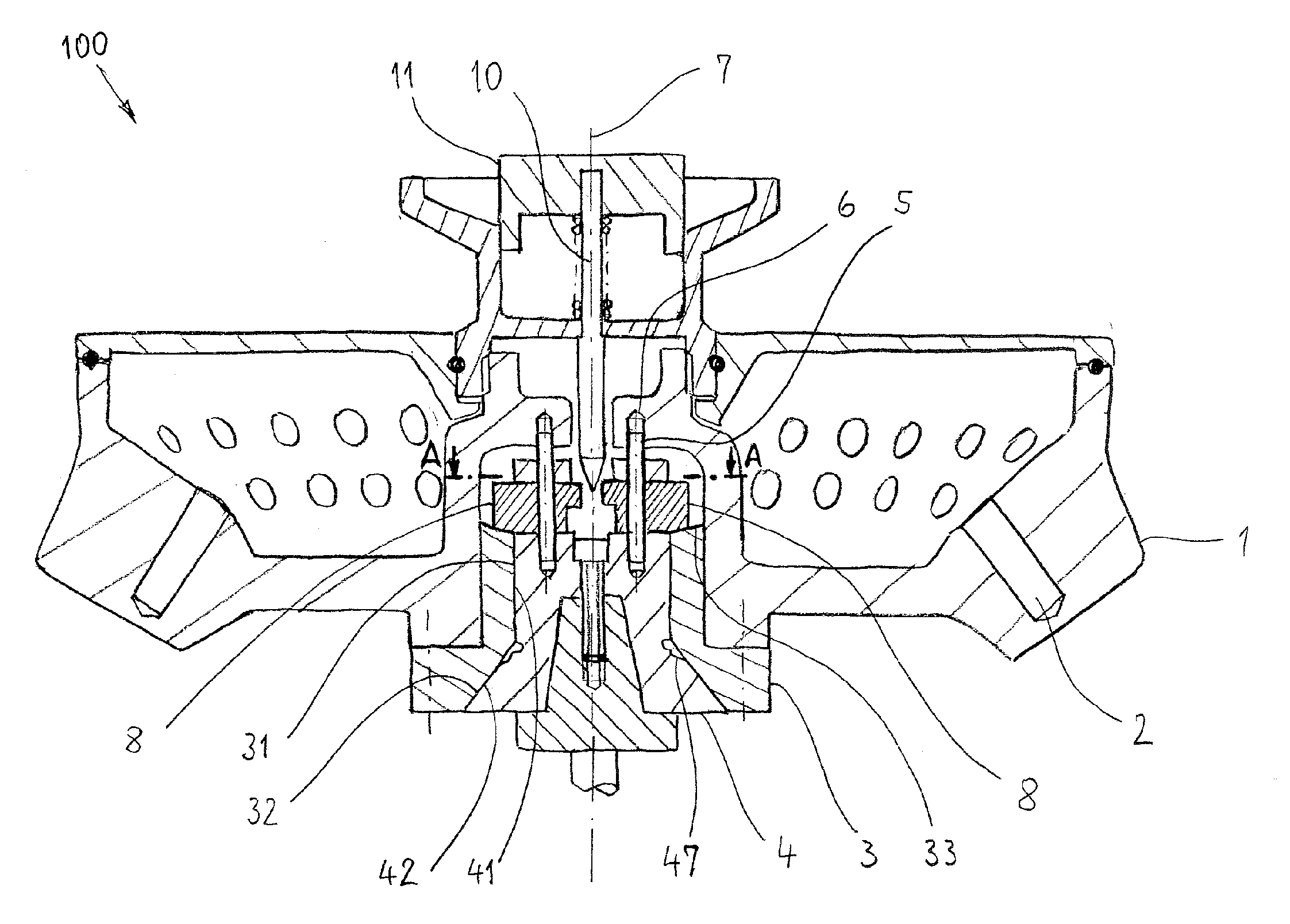
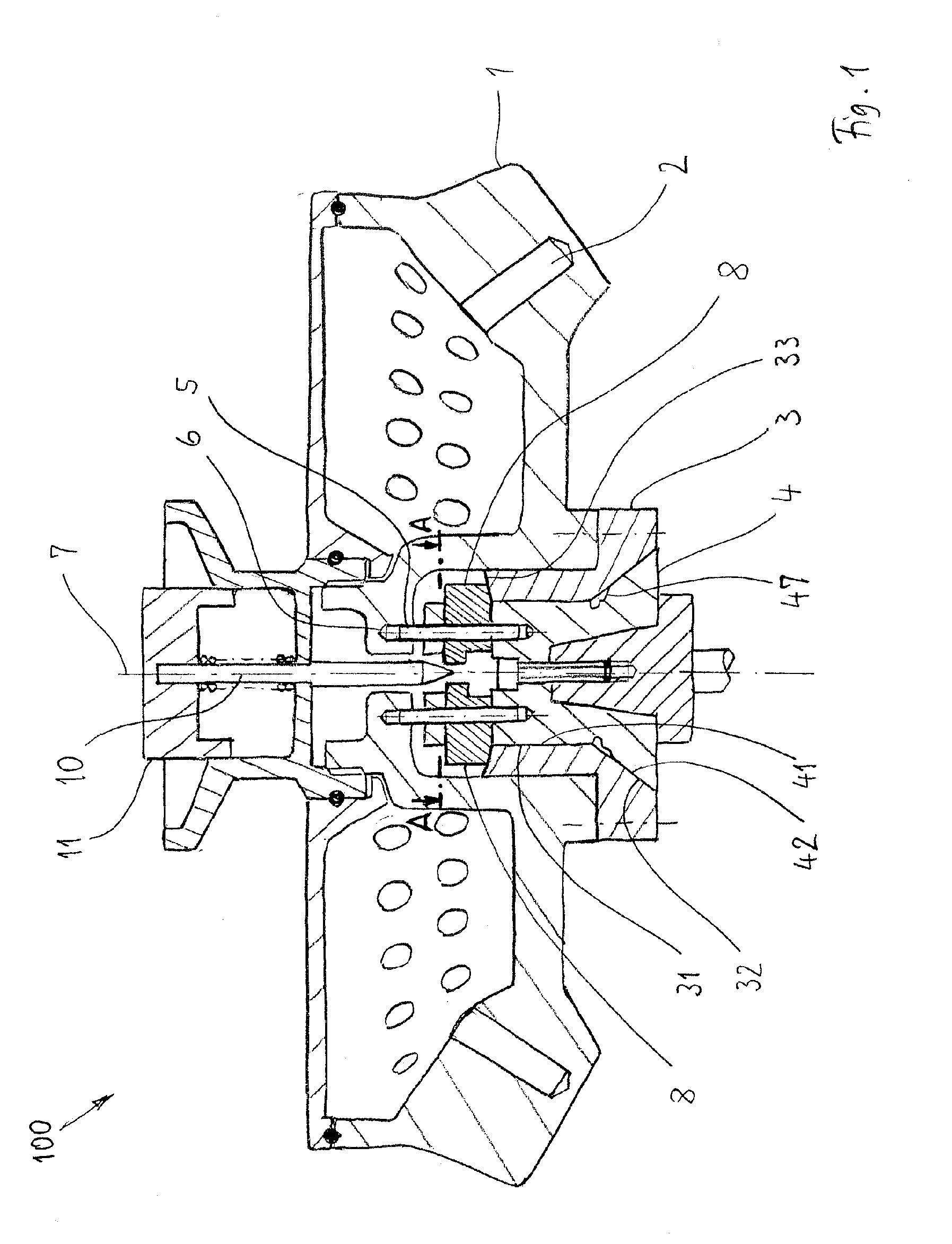
[0023]FIG. 1 shows a cross-sectional view of a centrifuge 100 in accordance with the invention without any substructure. Centrifuge 100 comprises a rotor 1 which comprises a plurality of recesses 2 for accommodating sample containers with substances to be centrifuged. A sleeve 3 is mounted on the rotor 1, which sleeve rests in an interlocking manner on a drive head 4. Two vertically extending connection elements 5 in the form of pins are attached to the drive head 4, which pins each engage in an interlocking manner in a recess 6 in rotor 1. In the embodiment as shown in FIG. 1 there are two connection elements 5 which are arranged symmetrically in relation to the rotary axis 7. It is also possible to provide more than two connection elements 5. During a rotary movement of the drive head 4 about the rotary axis 7, these connection elements 5 transmit a torque onto rotor 1, so that it can be made to rotate. It is achieved by the symmetric arrangement of the connection elements 5 that the torque is transmitted evenly onto the rotor 1.
[0024]In addition, the centrifuge 100 comprises in this embodiment two coupling elements 8 which are each arranged symmetrically in relation to the rotary axis 7 (also see FIG. 2, which shows a view along the line of intersection A-A in FIG. 1). The coupling elements 8 are arranged on the drive head 4 and are able to pivot to the side. The swivel axis 9 is formed by the connection element 5.
[0025]When the rotor 1 is to be connected with the drive head 4, rotor 1 is moved downwardly from the top in the direction towards the drive head 4. The sleeve 3 which is mounted on the rotor 1 meets a respectively outer edge 81 of the coupling elements 8 with its truncated cone surface 32, which coupling elements are pressed away from a stop 46 by a pressure spring 45. The coupling elements 8 are pivoted by the lowering of the sleeve 3 with its truncated cone surface 32 onto the respective edges 81 in such a way that the respective outer edge 81 comes to overlap the jacket line 44 of the drive head 4. The elongated part 82 of each coupling element 8 is pivoted in the direction towards the rotary axis 7 against the spring force of pressure spring 45.
[0026]The sleeve 3 or rotor 1 is able to slide past the coupling elements 8 during further lowering in the vertical direction until the truncated cone surface 32 rests on a corresponding truncated cone surface 42 of the drive head 4. The truncated cone surface 42 is used as a stop and delimits the downward movement of the rotor 1. In this position the coupling elements 8 can automatically pivot back to their former position, as a result of the spring force of the pressure spring 45 (see FIGS. 1 and 2). The elongated part 82 of each coupling element 8 protrudes beyond the jacket line 44 of the drive head 4, with each coupling element 8 touching the sleeve 3. The coupling elements form a quick-connect coupling, so that the rotor can be connected rapidly and without any tools with the drive head. If users wish to check whether the rotor 1 has been placed on the drive head 4, they can try to pull the rotor 1 upwardly. Since rotor 1 or sleeve 3 rests on the coupling elements 8, an upward vertical displacement is not possible. The user thus recognizes that the rotor is rigidly connected with the drive head 4.
[0027]The coupling elements 8 can be detached from the sleeve 3 when an actuating element 10 is moved vertically downwardly along the rotary axis 7 (see FIG. 1). The actuating element 10, which in this embodiment is connected with a resiliently pretensioned pushbutton 11, has a conical end which is able to act upon a coupling tooth 84 of the coupling element 8 (see FIG. 2). The conical end exerts a force perpendicularly to the rotary axis 7, so that the coupling element 8 can be pivoted in such a way until the outer edge 81 comes to overlap again with the jacket line 44 or is displaced even further into the drive head. Rotor 1 can then be pulled upwardly again and be detached from the drive head 4.
[0028]FIG. 3 shows a detailed view of the contact of the coupling element 8 with the sleeve 3. The coupling element 8 has a ramp surface 83 which is inclined at an angle α relative to the horizontal line. The ramp surface 83 touches the corresponding ramp surface 33 of the sleeve 3 in an interlocking manner, which is also inclined at an angle α relative to the horizontal line. The coupling element 8 and the sleeve 3 each form a wedge body as a result of the ramp surfaces 33, 83. If a lifting force FA acts upon the rotor 1 or sleeve 3 as a result of a high rotary speed, the reaction forces shown in FIG. 3 will be obtained on the surface pair 33, 83 during the cooperation with a coupling element 8. A normal force FN acts perpendicularly to the ramp surface 33 on the coupling element 8, with a holding force FH=FN*μ0 acting, with μ0 being the coefficient of friction. The holding force FH is counteracted by a restoring force FR of the coupling element 8. The coupling element 8 cannot be pivoted laterally as a result of the lifting force FA when the following relationship is maintained between the angle α and the coefficient of friction μo:
0
[0029]At a coefficient of friction of 0.3, as is present in the pairing of steel/steel with dry surface (friction of solid bodies), the angle α must be smaller than 16.7°. Self-locking also occurs during standstill of the rotor. When the coupling element 8 is pressed to the side by a pressure spring 45, a spring force FF acts on the coupling element 8 in addition to the holding force FH. A speed-dependent centrifugal force Fz is also added in a rotation of the rotor 1, so that the total holding force FHges is calculated as follows in a rotating rotor:
FHges=μ0*FA cos α+FF cos α+FZ cos α
[0030]It is shown in FIG. 4 how the ratio of FR to FH changes depending on the speed n. At a ratio of FR:FH=1 there is a borderline case in which self-locking is just about achieved. At an angle α=15°, the ratio of FR:FH is less than 1 in the pairing of materials as chosen here with a coefficient of friction of 0.3 each (see FIG. 4). With increasing speed the amount contributed by the centrifugal force will increase, so that the ratio of FR:FH will decrease with rising speed n. The locking of the rotor will thus become more secure with increasing speed.
[0031]FIG. 5 shows a detail in the region of the contact between the drive head 4 and the sleeve 3. The drive head 4 has an accumulation of dirt 48 of thickness t in the region of the truncated cone. When the sleeve 3 or rotor 1 is lowered, the truncated cone surface 32 of the sleeve no longer reaches the truncated cone surface 42 of the drive head 4, but remains at a height which is higher by the amount h than if no dirt accumulation were present. The sensitivity to such an accumulation of dirt is lower the larger the truncated cone angle β, since thus the difference in height to be bridged by the coupling elements between a clean and dirty cone will become smaller. Since the available space for the movement of the coupling elements 8 is limited and one can assume a dirt accumulation of a maximum of 0.5 mm, the truncated cone angle is approx. 35° in this embodiment.
[0032]The influence of dirt accumulation on the cylinder surface 41 can be kept at a low level when recesses 47 are provided in the region of the truncated cone surface 42 of the drive head. They will receive an accumulation of dirt disposed in the region of the cylinder surface 41 during the lowering of the sleeve 3 and will prevent that it will accumulate additionally on the truncated cone surface 42.
[0033]While the present invention has been illustrated by description of various embodiments and while those embodiments have been described in considerable detail, it is not the intention of applicant to restrict or in any way limit the scope of the appended claims to such details. Additional advantages and modifications will readily appear to those skilled in the art. The invention in its broader aspects is therefore not limited to the specific details and illustrative examples shown and described. Accordingly, departures may be made from such details without departing from the spirit or scope of Applicant's invention.

PUM

no PUM

Description & Claims & Application Information

We can also present the details of the Description, Claims and Application information to help users get a comprehensive understanding of the technical details of the patent, such as background art, summary of invention, brief description of drawings, description of embodiments, and other original content. On the other hand, users can also determine the specific scope of protection of the technology through the list of claims; as well as understand the changes in the life cycle of the technology with the presentation of the patent timeline. Login to view more.

Similar technology patents

Electric motor

ActiveUS20100308681A1easy to performvoltage decrease
Owner:MITSUBA CORP

Mass Spectrometry Data Analysis Method

ActiveUS20180019110A1easy to performbroaden scope
Owner:JEOL LTD

Monitor postion adjustment device

ActiveUS20100087951A1easy to perform
Owner:HONDA MOTOR CO LTD

Classification and recommendation of technical efficacy words

  • easy to perform

Display apparatus

InactiveUS20140267869A1easy to perform
Owner:OM DIGITAL SOLUTIONS CORP

Band saw blade

InactiveUS7036415B2easy to performimprove roughness
Owner:AMADA CO LTD
Why Eureka
Try Eureka