Method for controlling a flow of refrigerant to an evaporator

Active Publication Date: 2011-09-08
DANFOSS AS
View PDF4 Cites 7 Cited by
  • Summary
  • Abstract
  • Description
  • Claims
  • Application Information

AI Technical Summary

Benefits of technology

[0008]It is a further object of the invention to provide a method for controlling a flow of refrigerant to an evaporator, wherein an increased utilisation of the refrigeration capacity of the evaporator is obtained without risking damage to t

Problems solved by technology

In the case that liquid refrigerant is allowed to exit the evaporator there is a risk that this liquid refrigerant reaches the compressor, and this may in some cases cause damage to the compressor.
On the other hand, in the case that the liquid refrigerant evaporates while passing the first part of the evaporator, then the refrigeration capacity of the evaporator is not utilised to the full extent.
However, when the superheat value is zero it is impossible to know whether the evaporator is operating

Method used


Image

  • Method for controlling a flow of refrigerant to an evaporator
  • Method for controlling a flow of refrigerant to an evaporator
  • Method for controlling a flow of refrigerant to an evaporator

Examples


Embodiment Construction

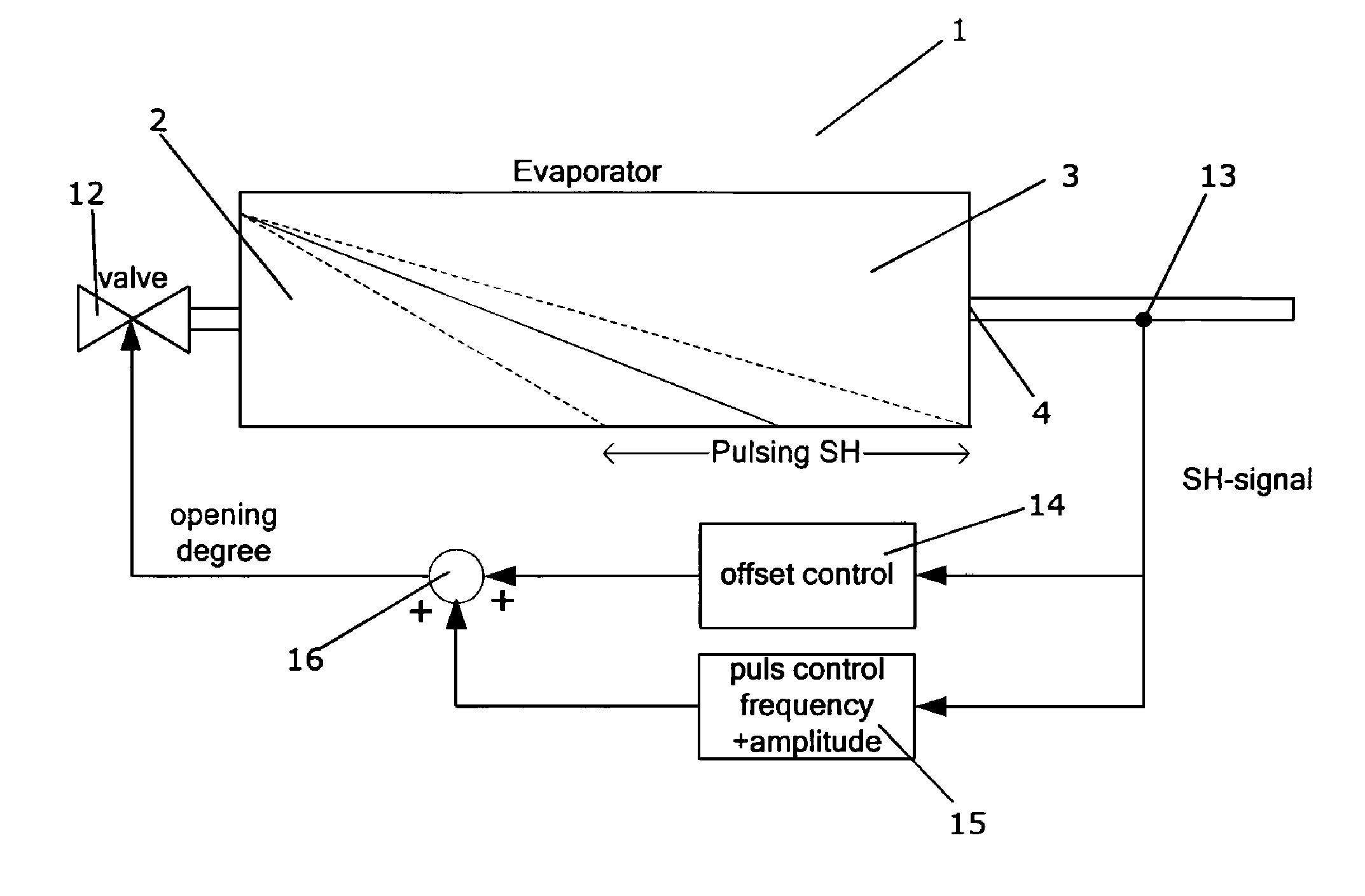
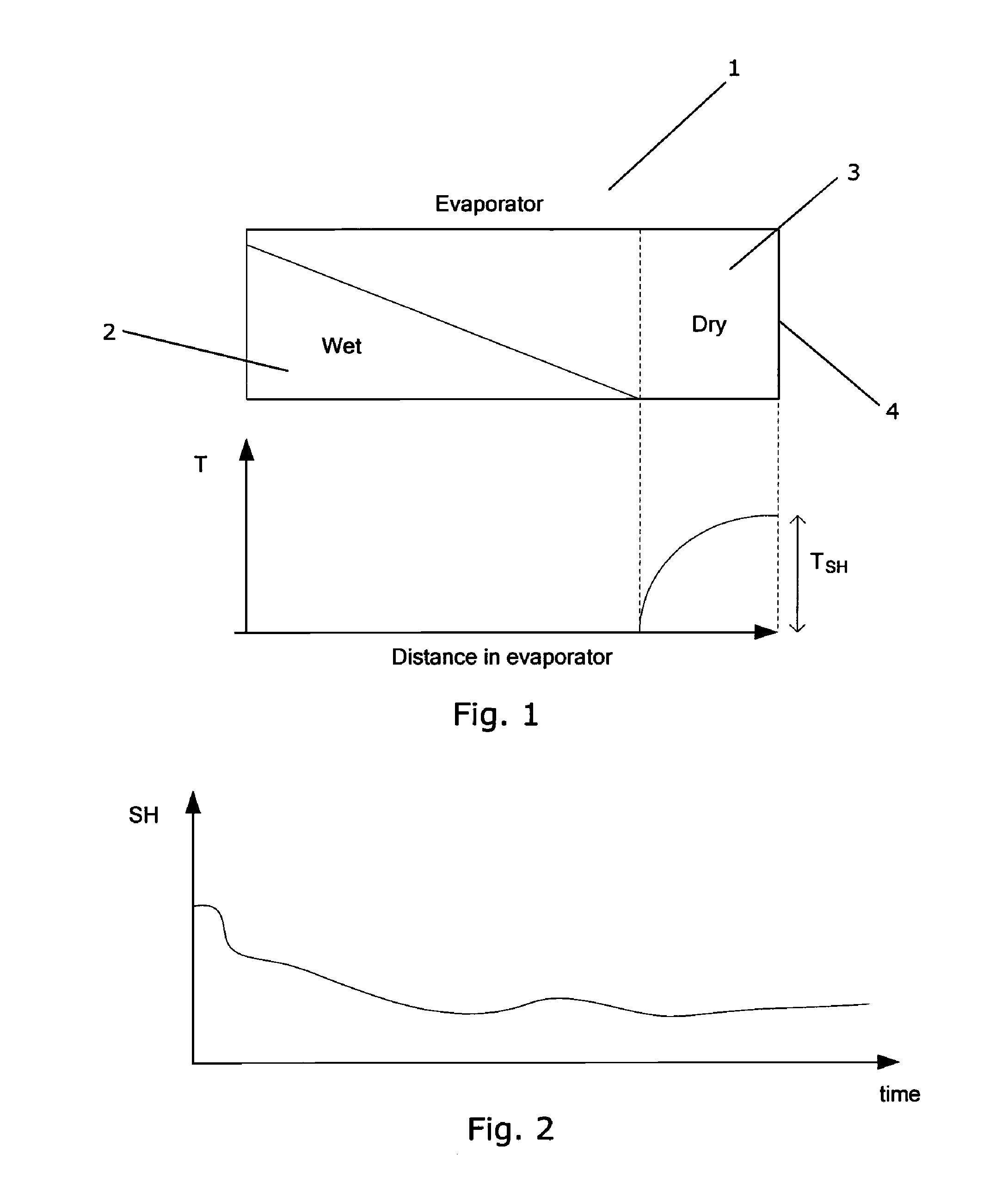
[0035]FIG. 1 shows an evaporator 1 during operation of a refrigeration system. The evaporator 1 has a first region 2 and a second region 3. The first region 2 contains refrigerant in a liquid / mixed state, i.e. the refrigerant in the first region 2 of the evaporator 1 is either in a liquid phase or it is a mixture of liquid and gaseous refrigerant. The second region 3 contains refrigerant in a purely gaseous phase. Accordingly, evaporation of refrigerant takes place in the first region 2 of the evaporator 1, but not in the second region 3 of the evaporator 1, i.e. only the part of the evaporator 1 which corresponds to the first region 2 is actually utilised.

[0036]The graph shown below the evaporator 1 illustrates the superheat value of the refrigerant as a function of position along the evaporator 1. It can be seen that the superheat value is zero in the first region 2 of the evaporator 1. As soon as the boundary between the first region 2 and the second region 3 is reached, the supe...


PUM


Abstract

A method for controlling a flow of refrigerant to an evaporator (1) arranged in a refrigeration system is disclosed. The refrigeration system further comprises an expansion valve (12) and a compressor, the expansion valve (12), the evaporator (1) and the compressor being arranged in a refrigerant flow path having refrigerant flowing therein. The method comprises the steps of increasing an opening degree of the expansion valve (12), thereby increasing a flow of refrigerant to the evaporator (1) sufficiently to substantially eliminate a dry zone (3) of the evaporator (1), decreasing the opening degree of the expansion valve (12) after a period of time has lapsed, and repeating the steps of increasing and decreasing the opening degree of the expansion valve (12). Thus, the opening degree of the expansion valve (12) is ‘pulsated’. This causes the superheat value of refrigerant leaving the evaporator (1) to ‘toggle’ between a zero level and a low, but positive, level. Thereby the average superheat value of the refrigerant leaving the evaporator (1) is decreased, and the refrigeration capacity of the evaporator (1) is utilised more efficiently. Simultaneously, it is ensured that the amount of liquid refrigerant being allowed to pass through the evaporator (1) is kept sufficiently low to prevent damage to the compressor.

Description

CROSS REFERENCE TO RELATED APPLICATIONS[0001]This application is entitled to the benefit of and incorporates by reference essential subject matter disclosed in International Patent Application No. PCT / DK2009 / 000200 filed on Sep. 4, 2009, Danish Patent Application No. PA 2008 01235 filed on Sep. 5, 2008.FIELD OF THE INVENTION[0002]The present invention relates to a method for controlling a flow of refrigerant to an evaporator which is arranged in a refrigeration system. The method of the present invention allows the refrigeration system to be controlled in a manner which ensures that the refrigerating capacity of the evaporator is utilized more efficiently than it is the case when using prior art methods.BACKGROUND OF THE INVENTION[0003]Refrigeration systems are often operated by adjusting a degree of opening of an expansion valve and / or by opening / closing an expansion valve, thereby controlling the amount of liquid refrigerant being supplied to an evaporator. It is desirable to cont...

Claims


Application Information

Patent Timeline
IPC IPC(8): F25B41/04
CPCF25B41/062F25B2341/0652Y02B30/72F25B2600/2521F25B2600/21Y02B30/70F25B41/347
Inventor LARSEN, LARS FINN SLOTHTHYBO, CLAUS
Owner DANFOSS AS
Why Eureka
Try Eureka