Method for controlling a flow of refrigerant to an evaporator

a technology of refrigerant flow and evaporator, which is applied in the direction of refrigeration components, mechanical equipment, lighting and heating apparatus, etc., can solve the problems of insufficient utilization of refrigeration capacity of evaporator, damage to compressor, and reaches of refrigerant, so as to reduce the complexity of the refrigeration system, increase the utilisation of the refrigeration capacity of the evaporator, and reduce the effect of component coun

Active Publication Date: 2015-12-22
DANFOSS AS
View PDF8 Cites 1 Cited by
  • Summary
  • Abstract
  • Description
  • Claims
  • Application Information

AI Technical Summary

Benefits of technology

[0008]It is a further object of the invention to provide a method for controlling a flow of refrigerant to an evaporator, wherein an increased utilisation of the refrigeration capacity of the evaporator is obtained without risking damage to the compressor.
[0009]It is an even further object of the invention to provide a method for controlling a flow of refrigerant to an evaporator, the method allowing the component count and the complexity of the refrigeration system to be reduced.
[0011]increasing an opening degree of the expansion valve, thereby increasing a flow of refrigerant to the evaporator sufficiently to substantially eliminate a dry zone of the evaporator,
[0017]The steps of increasing and decreasing the opening degree are repeated, preferably multiple times. Thereby the opening degree of the expansion valve is ‘pulsating’. The ‘pulsating’ opening degree of the expansion valve causes the superheat value of the refrigerant leaving the evaporator to ‘toggle’ between zero and a low, but positive, value. Thereby the average value of the refrigerant leaving the evaporator is decreased as compared to the situation where the superheat value is kept at a low, positive level constantly, because the superheat value is periodically allowed to decrease to the zero level. Thereby the refrigerating capacity of the evaporator is utilised more efficiently, i.e. the refrigeration system is operated in a more efficient manner. Simultaneously, it is ensured that only a small amount of liquid refrigerant is allowed to pass through the evaporator, because the superheat value is only allowed to remain at the zero level for a short period of time before the opening degree of the expansion valve is once again decreased, thereby increasing the superheat to a positive value. Accordingly, the risk of causing damage to the compressor due to liquid refrigerant being passed through the evaporator is eliminated, or at least reduced considerably.
[0026]Alternatively or additionally, the method may comprise monitoring the superheat value of the refrigerant leaving the evaporator and determining if the superheat value is increasing or decreasing. If the monitored superheat value reveals that the superheat value is ‘too high’, i.e. it has not yet reached the zero level, even though the opening degree of the expansion valve has been increased, but that the superheat value is decreasing, then it may be decided to maintain the opening degree of the expansion valve at the current level, or even to decrease the opening degree of the expansion valve to allow it to ‘pulsate’ as described above. This is because the decreasing superheat value shows that the superheat value is ‘on the right track’. The system comprises a certain ‘inertia’ in the sense that an increase in opening degree is reflected in a decrease in superheat value with some delay. Thus, the approach described above prevents the superheat value from decreasing so much that an excessive amount of liquid refrigerant is allowed to pass through the evaporator.

Problems solved by technology

In the case that liquid refrigerant is allowed to exit the evaporator there is a risk that this liquid refrigerant reaches the compressor, and this may in some cases cause damage to the compressor.
On the other hand, in the case that the liquid refrigerant evaporates while passing the first part of the evaporator, then the refrigeration capacity of the evaporator is not utilised to the full extent.
However, when the superheat value is zero it is impossible to know whether the evaporator is operating in an optimal manner, i.e. the liquid refrigerant is exactly evaporated in the evaporator, or whether a large amount of liquid refrigerant is passing through the evaporator.
However, this has the consequence that the refrigeration capacity of the evaporator is not fully utilised.
It is, however, a disadvantage that the solution suggested in this paper requires an additional heat exchanger, since this increases the costs of producing the refrigeration system, as well as the complexity of the system.

Method used


Image

  • Method for controlling a flow of refrigerant to an evaporator
  • Method for controlling a flow of refrigerant to an evaporator
  • Method for controlling a flow of refrigerant to an evaporator

Examples


Embodiment Construction

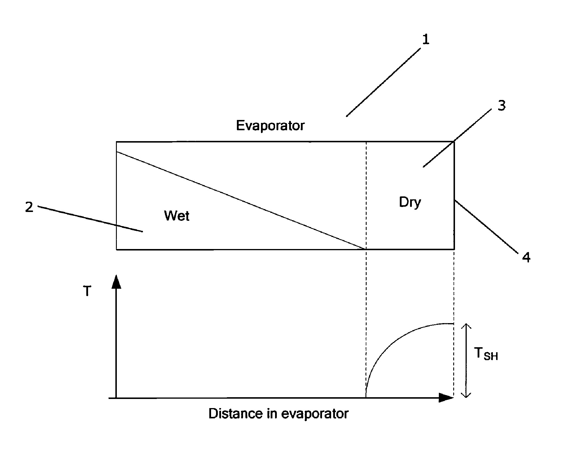
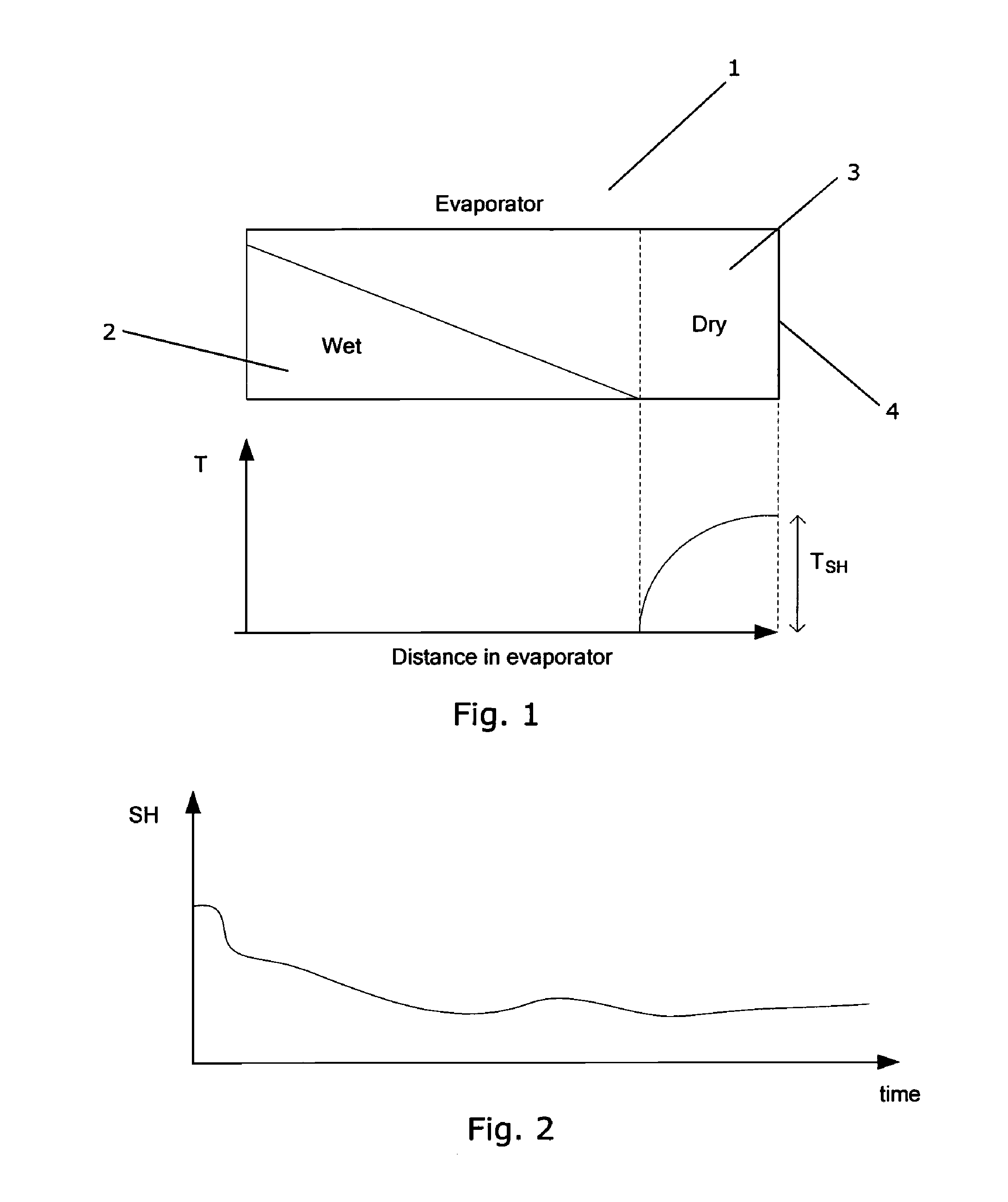
[0035]FIG. 1 shows an evaporator 1 during operation of a refrigeration system. The evaporator 1 has a first region 2 and a second region 3. The first region 2 contains refrigerant in a liquid / mixed state, i.e. the refrigerant in the first region 2 of the evaporator 1 is either in a liquid phase or it is a mixture of liquid and gaseous refrigerant. The second region 3 contains refrigerant in a purely gaseous phase. Accordingly, evaporation of refrigerant takes place in the first region 2 of the evaporator 1, but not in the second region 3 of the evaporator 1, i.e. only the part of the evaporator 1 which corresponds to the first region 2 is actually utilised.

[0036]The graph shown below the evaporator 1 illustrates the superheat value of the refrigerant as a function of position along the evaporator 1. It can be seen that the superheat value is zero in the first region 2 of the evaporator 1. As soon as the boundary between the first region 2 and the second region 3 is reached, the supe...


PUM


Abstract

A refrigeration system includes an expansion valve and a compressor, the expansion valve, the evaporator and the compressor being arranged in a refrigerant flow path having refrigerant flowing therein. A method for controlling a flow of refrigerant to an evaporator includes steps of increasing an opening degree of the expansion valve, thereby increasing a flow of refrigerant to the evaporator sufficiently to substantially eliminate a dry zone of the evaporator, decreasing the opening degree of the expansion valve, and repeating the steps of increasing and decreasing. This causes the superheat value of refrigerant leaving the evaporator to ‘toggle’ between a zero level and a low, but positive, level. Thereby the refrigeration capacity is utilized more efficiently. Additionally, sufficiently low amount of liquid refrigerant is allowed to pass through the evaporator to prevent damage to the compressor.

Description

CROSS REFERENCE TO RELATED APPLICATIONS[0001]This application is entitled to the benefit of and incorporates by reference essential subject matter disclosed in International Patent Application No. PCT / DK2009 / 000200 filed on Sep. 4, 2009, Danish Patent Application No. PA 2008 01235 filed on Sep. 5, 2008.FIELD OF THE INVENTION[0002]The present invention relates to a method for controlling a flow of refrigerant to an evaporator which is arranged in a refrigeration system. The method of the present invention allows the refrigeration system to be controlled in a manner which ensures that the refrigerating capacity of the evaporator is utilized more efficiently than it is the case when using prior art methods.BACKGROUND OF THE INVENTION[0003]Refrigeration systems are often operated by adjusting a degree of opening of an expansion valve and / or by opening / closing an expansion valve, thereby controlling the amount of liquid refrigerant being supplied to an evaporator. It is desirable to cont...

Claims


Application Information

Patent Timeline
Patent Type & Authority Patents(United States)
IPC IPC(8): F25B41/04F25B41/06
CPCF25B41/062F25B2341/0652Y02B30/72F25B2600/2521F25B2600/21Y02B30/70F25B41/347
Inventor LARSEN, LARS FINN SLOTHTHYBO, CLAUS
Owner DANFOSS AS
Why Eureka
Try Eureka