Cartridge Unit and Trap for Sewer Gas & Odor Containment

a technology of sewer gas and odor containment, which is applied in the field of odor barrier, can solve the problems that the type of seal does not effectively stop urine odor, and achieve the effect of balancing the entire mechanism and improving the seal

Inactive Publication Date: 2011-09-15
CADAVID DANIEL OSORIO
View PDF19 Cites 13 Cited by
  • Summary
  • Abstract
  • Description
  • Claims
  • Application Information

AI Technical Summary

Benefits of technology

Further, a sealing disk is attached to the first cylindrical device using a spring locking mechanism. Also attached to the first cylindrical device is a seal attached to the top of the central column of the first cylindrical device so that the seal prevents fluids or gases to flow upwards through the first cylindrical device and blocks motion of a second cylindrical device. The spring locking mechanism further comprises a second cylindrical device inserted coaxially into the first cylindrical device such that the second cylindrical device has a flange at its top to respond to the motion of a spring arranged coaxially around the second cylindrical device and designed to compress and decompress against the second cylindrical device's flange and a ledge inside of the first cylindrical device.
To enable the attachment of the sealing disk with the second cylindrical device, the locking member is inserted coaxially underneath the sealing disk and passing through the sealing disk and passing through and threaded into the second cylindrical device so as to lock together the sealing disk and the second cylindrical device so as to engage the coaxially arranged spring. The system also includes an o-ring attached to the sealing disk so as to make a better seal between the sealing disk and the first cylindrical device and a weight disk to better balance the entire mechanism.

Problems solved by technology

However, this type of seal does not effectively stop urine odor from flowing up through the urinal.

Method used


Image

  • Cartridge Unit and Trap for Sewer Gas & Odor Containment
  • Cartridge Unit and Trap for Sewer Gas & Odor Containment
  • Cartridge Unit and Trap for Sewer Gas & Odor Containment

Examples


Embodiment Construction

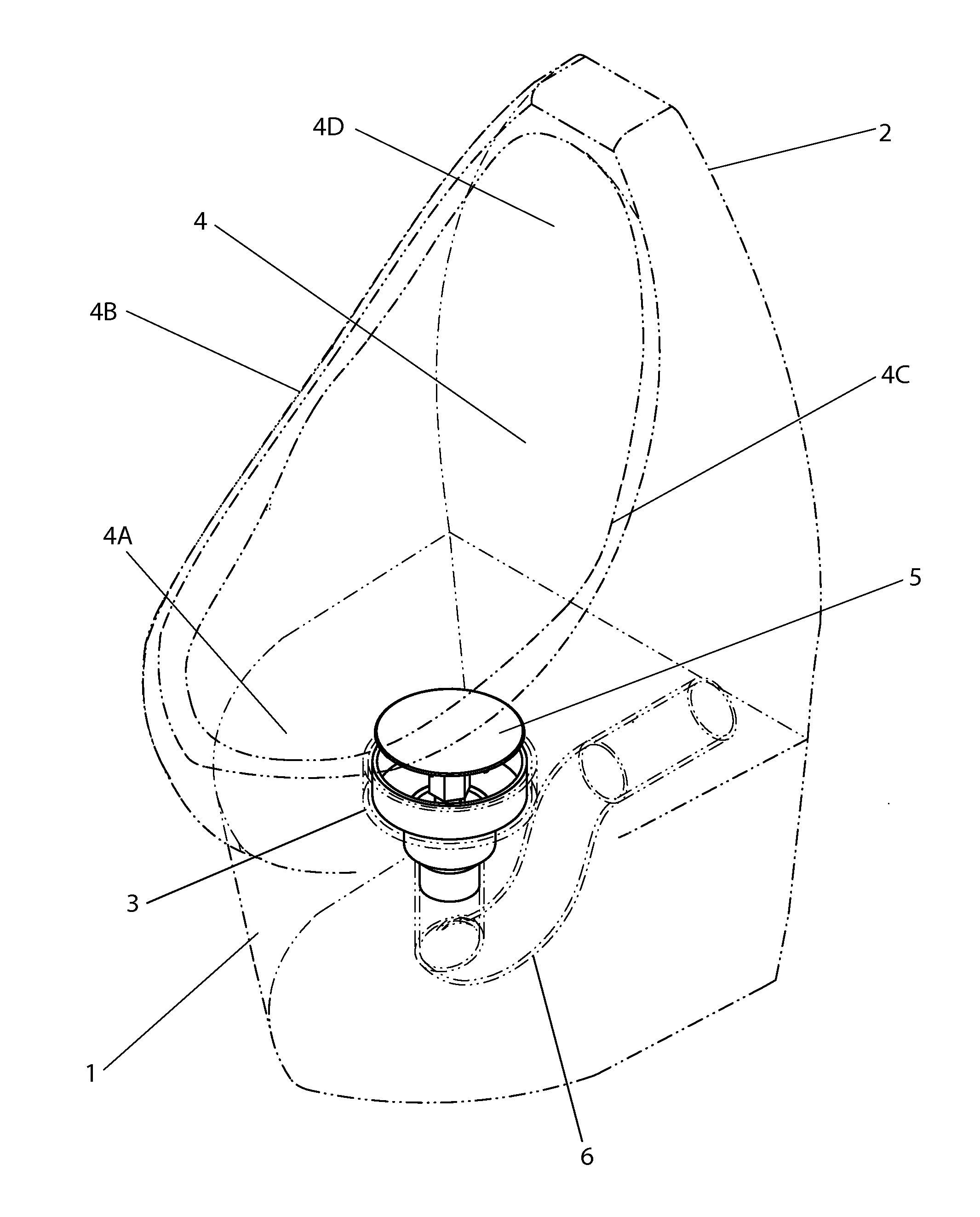
FIG. 1 shows a complete assembly 1, including a vitreous china urinal 2, a cartridge unit 5 according to the present invention and a P-trap 6. The illustrated urinal 2 being a wall mounted unit attached above a floor surface (not shown). The vitreous china urinal 2 includes a back wall region 4 and side-wall regions 4B, 4C which extend from a lower region 4A of the urinal 2 to an upper region 4D. The urinal 2 further includes a cylindrical opening 3 located on its lower region 4A in a watertight connection with the cartridge unit 5 configured to allow urine received on the urinal lower region 4A to be directed to a drain as shown in FIG. 2.

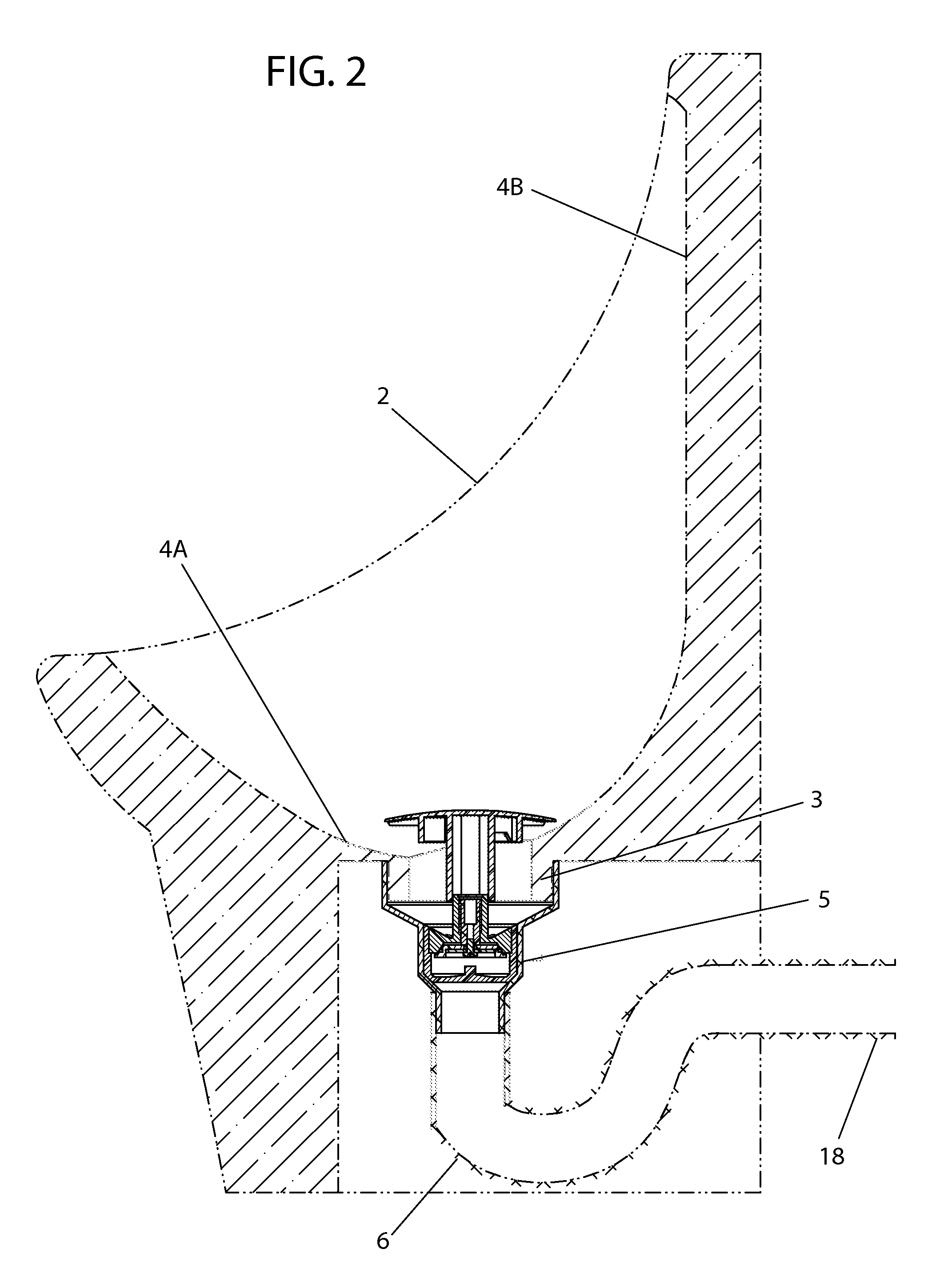
FIG. 2 illustrates a cross section of the urinal assembly shown in FIG. 1 and includes a drain connection line 18. Here a P-trap 6 is connected to a drain connection line 18 for providing a pathway from the urinal lower region 4A to a sewer drain (not shown).

FIG. 3 illustrates the cartridge unit used in the urinal shown in FIGS. 1-2. The cartridge...


PUM


Abstract

A cartridge unit for use with a urinal is disclosed that does not need water to work nor does it use a body of oily liquid sealant as an odor barrier. The odor trap cartridge unit used in this urinal has a spring locking mechanism that works as a valve. It is opened by liquid weight when the urinal is used and lets urine or any other liquid pass downwardly through it and prevents odors from flowing back up towards the room. The cartridge unit has a few disks, two main cylindrical devices, a spring, a fastener, an o-ring, and a coupling; these all operate to open and close a spring sealed trap. These are all placed within a unique three-sized shell that supports the entire cartridge and is fitted into a urinal opening. An umbrella shaped part completes the cartridge by protecting its components from violent fluid flow.

Description

CROSS REFERENCE TO RELATED APPLICATIONSN / ASTATEMENT REGARDING FEDERALLY SPONSORED RESEARCH OR DEVELOPMENTN / ACOPYRIGHT NOTICEA portion of the disclosure of this patent document contains material that is subject to copyright protection. The copyright owner has no objection to the facsimile reproduction by anyone of the patent document or patent disclosure as it appears in the United States Patent and Trademark Office patent file or records, but otherwise reserves all copyrights whatsoever.BACKGROUND(1) Field of the InventionThe present invention relates to improvements in odor containment for urinals and more particularly an odor barrier that does not require the use of any oily liquid.(2) Description of the Related ArtCurrent TechniquesIn our modern world, efficient and effective utilization of resources has become a hallmark of the environmental ethos. Conservation of fresh water, a primary natural resource, has finally arrived to the common household and to businesses. In the home ...

Claims


Application Information

Patent Timeline
Patent Type & Authority Applications(United States)
IPC IPC(8): E03D11/00
CPCE03C1/281E03D13/00E03C1/298Y10T137/4478Y10T137/7922Y10T137/7932Y10T137/7936
Inventor CADAVID, DANIEL OSORIO
Owner CADAVID DANIEL OSORIO
Why Eureka
Try Eureka