
Cyclone Construction for a Surface Cleaning Apparatus

Active Publication Date: 2011-09-15
OMACHRON INTPROP
View PDF16 Cites 72 Cited by
  • Summary
  • Abstract
  • Description
  • Claims
  • Application Information

AI Technical Summary

Benefits of technology

[0006]A dirt collection chamber having an increased dirt capacity may also be provided by positioning the dirt collection chamber at least partially under the cyclone chamber and, preferably the dirt collection chamber may extend under the entire cyclone chamber. A surface cleaning apparatus, such as an upright vacuum cleaner may have the suction motor and the cyclone provided on the upper section. The cyclone is preferably provided above the suction motor so that the suction motor is at a lower height on the upper section, thereby reducing the hand weight of the upper section. In order to permit the air to flow to the suction motor from the cyclone with reduced back pressure, the cyclone air outlet may extend through the dirt collection chamber (e.g., the cyclone air outlet may have an extension of the vortex finder extend through the dirt collection chamber. In order to empty the dirt collection chamber, the bottom may be openable. The extension may be mounted to the cyclone chamber and remain in position when the bottom is opened. Alternately, the extension may be affixed to the bottom and therefore removed when the bottom is opened. Alternately, part may be affixed to the bottom and part to the cyclone so that part of the extension is removed.

Problems solved by technology

Therefore, when the wall is opened, the plate is moved out of its closed position and material collected in the dirt collection chamber and the cyclone chamber may fall out.
Accordingly, despite the height of the bin, the plate or floor may be moved sufficiently so that material may fall out of the cyclone chamber and the dirt collection chamber essentially unimpeded.

Method used


Image

  • Cyclone Construction for a Surface Cleaning Apparatus
  • Cyclone Construction for a Surface Cleaning Apparatus
  • Cyclone Construction for a Surface Cleaning Apparatus

Examples


Embodiment Construction

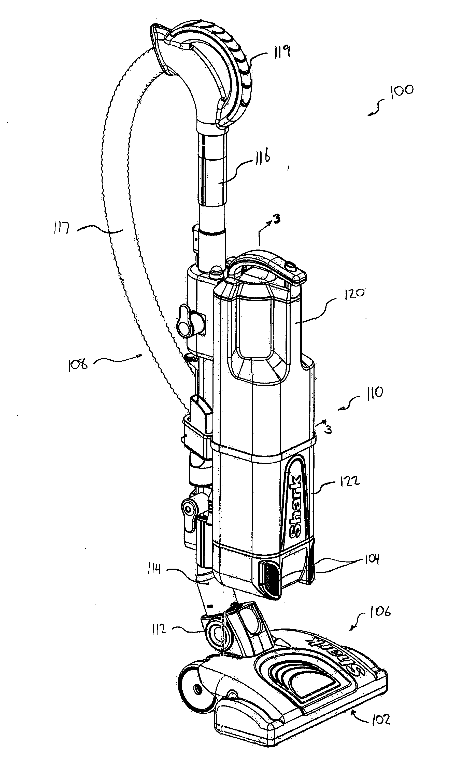
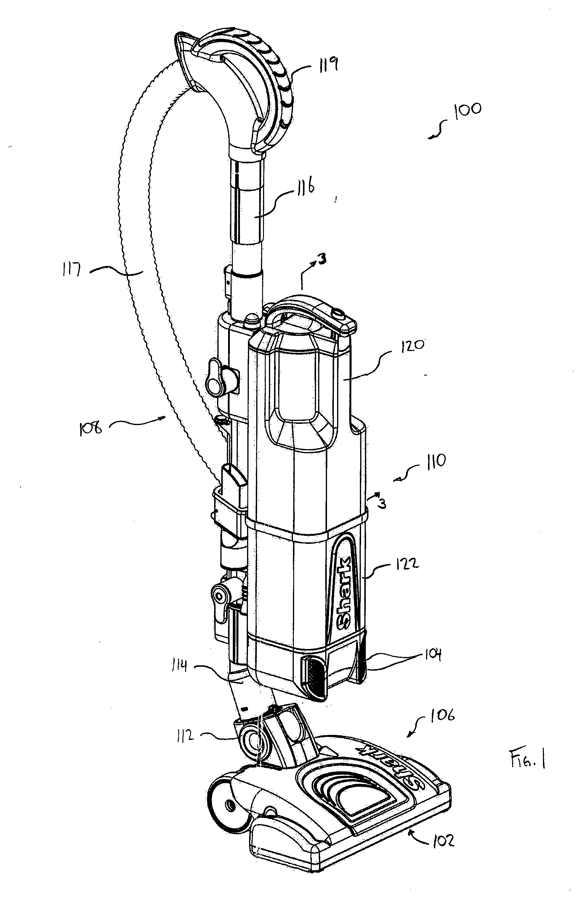
[0060]Referring to FIG. 1, a first embodiment of a surface cleaning apparatus 100 is shown. In the embodiment shown, the surface cleaning apparatus 100 is an upright vacuum cleaner. In alternate embodiments, the surface cleaning apparatus may be another suitable type of surface cleaning apparatus, such as a canister type vacuum cleaner, and hand vacuum cleaner, a stick vac, a wet-dry type vacuum cleaner or a carpet extractor.

[0061]Referring still to FIG. 1, the surface cleaning apparatus 100 has a dirty air inlet 102, a clean air outlet 104, and an air flow passage extending therebetween. In the embodiment shown, the dirty air inlet 102 is provided in a surface cleaning head 106. From the dirty air inlet 102, the airflow passage extends through the surface cleaning head 106, and through an air conduit 108, to a suction and filtration unit 110. The clean air outlet 104 is provided in the suction and filtration unit 110. Optionally, the suction and filtration unit 110 can be releasabl...


PUM


Abstract

The surface cleaning apparatus includes a cyclone positioned in am air flow passage. The cyclone has a cyclone air inlet and a cyclone air outlet, a dirt outlet spaced from the cyclone air inlet, a cyclone chamber wall and a longitudinal axis. The surface cleaning apparatus also includes a dirt collection chamber in communication with the dirt outlet. The dirt collection chamber has an openable wall mounted to the surface cleaning apparatus by a hinge and a centrally positioned longitudinal axis, the openable wall has a centre and a hinge side. The surface cleaning apparatus also includes a plate positioned at an interface of the dirt collection chamber and the cyclone. The plate is moveably mounted to the openable wall. The surface cleaning apparatus also includes a biasing member biasing the plate towards the hinge side of the openable wall a suction motor positioned in the air flow passage.

Description

FIELD[0001]The disclosure relates to surface cleaning apparatuses, such as vacuum cleaners. Particularly, the disclosure relates to a cyclone for surface cleaning apparatuses having cyclone chamber, dirt collection chamber and a movable plate at the interface therebetween and / or an airflow conduit extending through the dirt collection chamber.INTRODUCTION[0002]The following is not an admission that anything discussed below is prior art or part of the common general knowledge of persons skilled in the art.[0003]Various constructions for surface cleaning apparatus such as vacuum cleaners are known. Currently, many surface cleaning apparatus are constructed using at least one cyclonic cleaning stage. The air is drawn into the vacuum cleaner through a dirty air inlet and conveyed to a cyclone inlet. The rotation of the air in the cyclone results in some of the particulate matter in the airflow stream being disentrained from the airflow stream. This material is then collected in a dirt c...

Claims


Application Information

Patent Timeline
IPC IPC(8): A47L9/16
CPCA47L9/1683
Inventor CONRAD, WAYNE ERNEST
Owner OMACHRON INTPROP
Features
  • Generate Ideas
  • Intellectual Property
  • Life Sciences
  • Materials
  • Tech Scout
  • Unparalleled Data Quality
  • Higher Quality Content
  • 60% Fewer Hallucinations
Learn More