Calculate Drop Delay for Flow Cytometry Systems and Methods

a flow cytometer and drop delay technology, applied in the field of flow cytometer systems and methods, can solve the problems of inability to accurately calculate drop delay, inability to use fluorescent beads to determine drop delay, and inability to achieve the necessary precision of drop delay calculation

Active Publication Date: 2011-09-15
BECKMAN COULTER INC
View PDF13 Cites 51 Cited by
  • Summary
  • Abstract
  • Description
  • Claims
  • Application Information

AI Technical Summary

Problems solved by technology

Use of fluorescent beads to determine drop delay, however, is undesirable because fluorescent beads can contaminate the flow cytometer.
Further, what are needed are systems and methods to avoid the use of iterative, trial-and-error operations, which are time-consuming and can lack the necessary precision of drop delay calculation.

Method used


Image

  • Calculate Drop Delay for Flow Cytometry Systems and Methods
  • Calculate Drop Delay for Flow Cytometry Systems and Methods
  • Calculate Drop Delay for Flow Cytometry Systems and Methods

Examples


Embodiment Construction

[0031]The following detailed description of systems and methods for calculating drop delay refers to the accompanying drawings that illustrate exemplary embodiments. Unless otherwise noted, all embodiments and examples should be considered prophetic examples. Other embodiments are possible. Modifications can be made to the embodiments described herein without departing from the spirit and scope of the present invention. Therefore, the following detailed description is not meant to be limiting. Further, it would be apparent to one of skill in the art that the systems and methods described below can be implemented in many different embodiments of hardware, software, and / or firmware. Any actual hardware, software, and / or firmware described are not meant to be limiting.

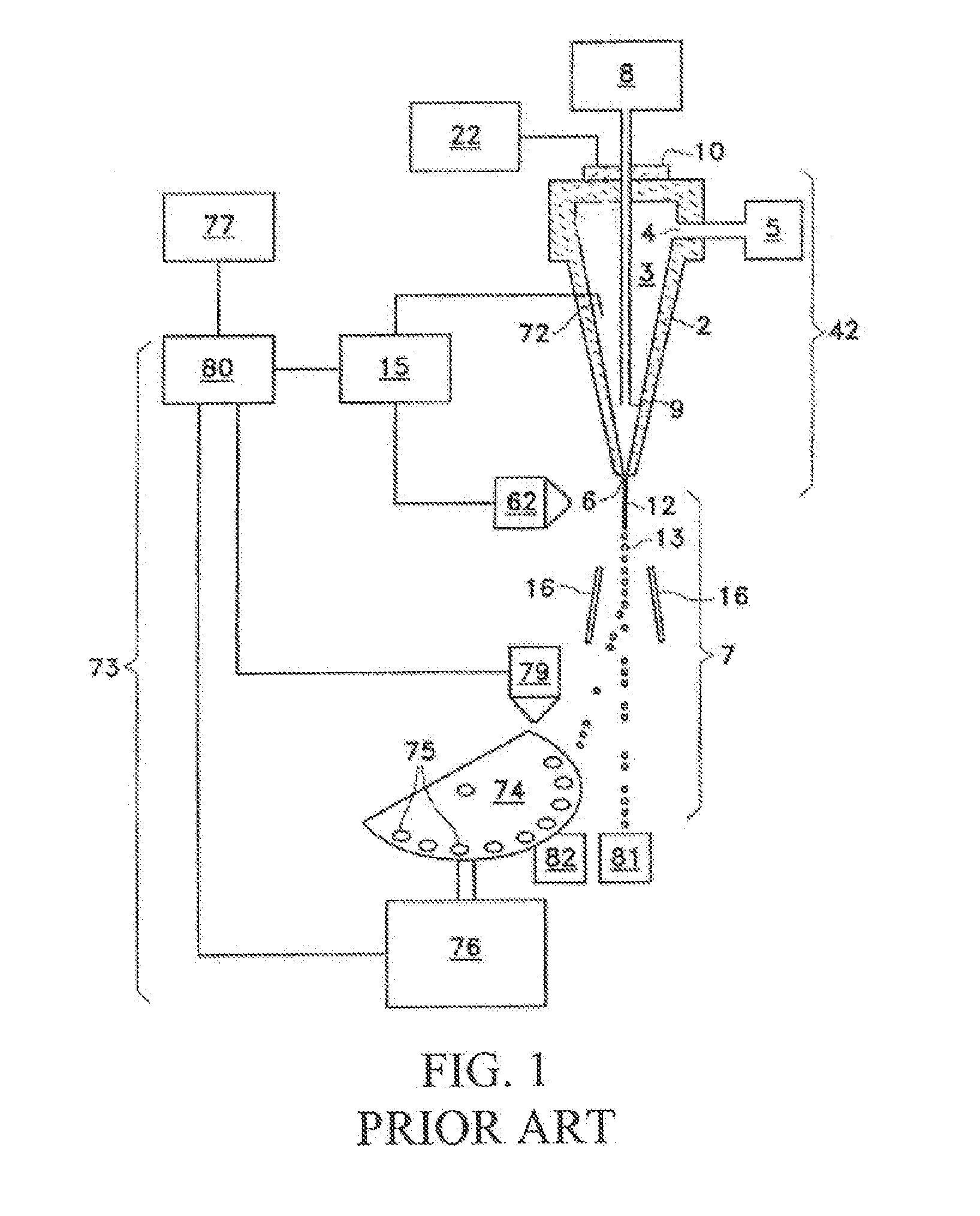
[0032]FIG. 1 is a schematic of a prior art flow cytometer system, as taught in U.S. Pat. No. 5,643,796, which was incorporated by reference above. FIG. 1 is presented to show the basic parts of a flow cytometer system, wh...


PUM

PropertyMeasurementUnit
frequencyaaaaaaaaaa
sizeaaaaaaaaaa
widthaaaaaaaaaa

Abstract

A method of calculating a drop delay in a stream of a flow cytometer. In one embodiment the method includes the steps of determining a widths plot by measuring the width of a stream based on an image of the stream and setting drop delay based on the widths plot. In another aspect the invention relates to a flow cytometer system for automatically calculating drop delay. In one embodiment the flow cytometer system includes means for determining a widths plot based on an image of the stream; and means for calculating drop delay based on the widths plot.

Description

PRIORITY CLAIM[0001]This patent application claims priority pursuant to 35 U.S.C. §119(e) to U.S. Provisional Patent Application 61 / 311,956, filed on Mar. 9, 2010, which is hereby incorporated by reference in its entirety.BACKGROUND[0002]1. Field of the Invention[0003]The present invention relates to systems and methods for flow cytometry. More specifically, the present invention relates to systems and methods for calculating drop delay in a flow cytometer.[0004]2. Background Art[0005]In the field of flow cytometry, a hydrodynamic focusing technique is used to separate and align analyte particles within a stream. An oscillator perturbs the stream as it is released from a nozzle of the flow cytometer. The perturbation results in droplets containing individual analyte particles. Just prior to breaking off from the stream, the droplets can be electrically charged and an electrical field downstream from the break-off point can be used to deflect and sort the charged particle. As part of...

Claims


Application Information

Patent Timeline
Patent Type & Authority Applications(United States)
IPC IPC(8): G06K9/00G01N21/00H04N7/18
CPCG01N15/1427Y10T436/115831G01N2015/149G01N2015/1406
Inventor NECKELS, DAVID C.COURTER, KEVIN C.
Owner BECKMAN COULTER INC
Why Eureka
Try Eureka