Anchorage systems and devices

a technology of anchorage system and device, applied in the direction of roofs, transportation items, manufacturing tools, etc., can solve the problems of difficult inserting and sliding of devices into positions, complex mechanisms, etc., and achieve the effect of reducing play or “rattle”

Active Publication Date: 2011-09-22
C N UNWIN
View PDF9 Cites 10 Cited by
  • Summary
  • Abstract
  • Description
  • Claims
  • Application Information

AI Technical Summary

Benefits of technology

[0009]One preferred object herein is to provide anchorages with novel means for reducing play or “rattle”.

Problems solved by technology

In general a tight fit of the feet in the track channel is avoided because it makes the devices hard to insert and slide into position.
Accordingly some known anchorage devices—particularly those used for rigid seat fixtures where play, shifting and rattling are especially undesirable—incorporate mechanisms for clamping or gripping against the track in the captive position.
However such mechanisms tend to be complex in structure e.g. requiring a tall construction, or central access to a long-form anchor, or are awkward to operate, or are incompatible with systems using insertable feet in scalloped track.

Method used


Image

  • Anchorage systems and devices
  • Anchorage systems and devices
  • Anchorage systems and devices

Examples


Embodiment Construction

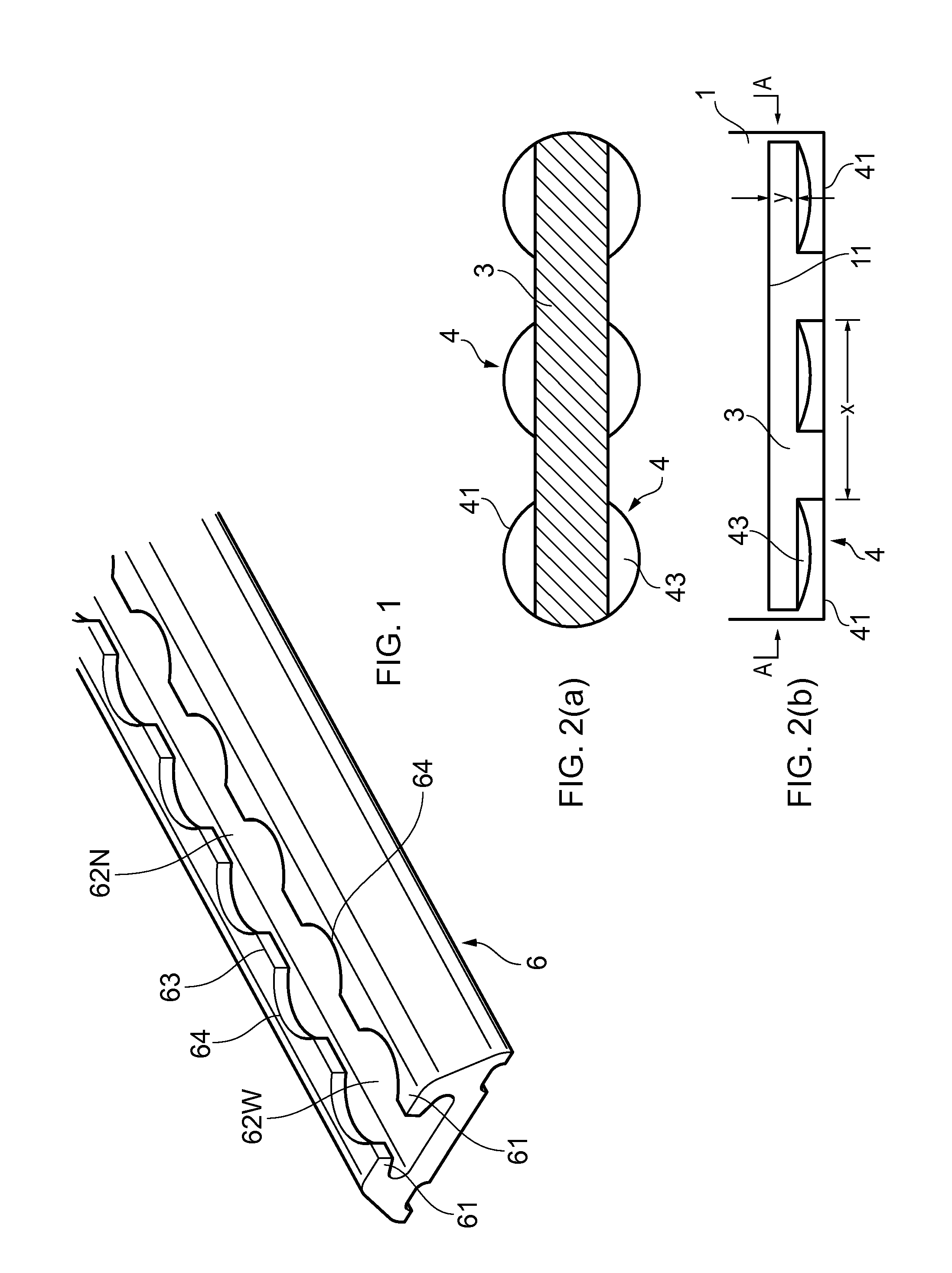
[0029]The conventional anchorage formation shown in FIG. 2 comprises three feet (or pairs of feet) 4 projecting out laterally to either side of a central keel formation 3. FIG. 2(b) also shows a top body portion 1 which enlarges laterally above the keel 3, presenting a downwardly-directed surface 11 which in use rests on top of the track flanges 61. The anchorage formation has a flat bottom surface 41 common to the keel 3 and feet 4. The width of the keel 3 is always less than the width of the narrow parts 62N of the track channel, so that once the feet 4 have been dropped down through the cut-outs 64 forming the wide parts 62W, the formation can move freely along the track. Each foot 4 has a circular plan shape fitting easily through the circular-plan cut-outs 64 of the track, and provided by lateral projections with circularly-arcuate edges 41 from the side of the keel formation 3. Usually the top surfaces 43 of the feet 4 incline slightly outwardly and downwardly as shown, to mat...


PUM

PropertyMeasurementUnit
angleaaaaaaaaaa
angleaaaaaaaaaa
angleaaaaaaaaaa

Abstract

Anchorage devices are disclosed for use in an anchorage system, especially for vehicle seats, using a floor track having a longitudinal channel whose opening has opposed lips with a series of periodic circular cut-outs. The anchorage device has enlarged slidable feet (104) which are insertable into the opening of the track channel at the cut-outs, and when slid along are held captive beneath the lips of the track. A releasable locking mechanism is provided for locking the device longitudinally to the track, so that the feet (104) can be held in the captive position. Preferably the device has an elongate body, with the locking mechanism operated by a lever at one end. The top surfaces (143) of at least some of the feet (104) are longitudinally inclined relative to the longitudinal direction. When slid to the captive position they come into contact or near contact with the underside of the track lips, reducing or preventing rattle relative to the track.

Description

FIELD OF THE INVENTION[0001]This invention has to do with systems for anchoring articles by means of track or rail formations. It has particular application for anchoring objects in vehicles, such as vehicle furniture e.g. seats, and restraints such as straps and the like.BACKGROUND[0002]It is well known to adapt the floors of vehicles (such as vans, minibuses and coaches) for the securing of furniture, seating, wheelchairs or other objects at any of a range of locations with variable position according to need. Typically this is by one or more tracks fixed onto or integrated into the vehicle floor. The tracks have an upwardly-open internal channel, usually formed using extruded aluminum, and the top opening of the channel—extending the length of the track—is defined between opposed overhanging lips or flanges.[0003]The most popular track format (seen in FIG. 1) is “scalloped” track 6 in which the channel opening 62 is interrupted by a series of periodic enlargements, usually of a c...

Claims


Application Information

Patent Timeline
Patent Type & Authority Applications(United States)
IPC IPC(8): B60R11/00B23P17/04
CPCB60N2/01575B60N2/01508Y10T16/37Y10T29/49826B60N2/01516B64D11/0696B60P7/0815
Inventor HEARN, GARY ALEXANDERJOHNSTON-HYDE, STEPHEN
Owner C N UNWIN
Why Eureka
Try Eureka