System and method for severing a tubular

a tubular and tubular technology, applied in the direction of sealing/packing, drilling pipes, wellbore/well accessories, etc., can solve the problem that the leakage of subsurface fluids may pose an environmental threa

Active Publication Date: 2011-09-22
NAT OILWELL VARCO LP
View PDF112 Cites 35 Cited by
  • Summary
  • Abstract
  • Description
  • Claims
  • Application Information

AI Technical Summary

Problems solved by technology

Leakage of subsurface fluids may pose an envir

Method used


Image

  • System and method for severing a tubular
  • System and method for severing a tubular
  • System and method for severing a tubular

Examples


Embodiment Construction

[0024]The description that follows includes exemplary apparatus, methods, techniques, and instruction sequences that embody techniques of the inventive subject matter. However, it is understood that the described embodiments may be practiced without these specific details.

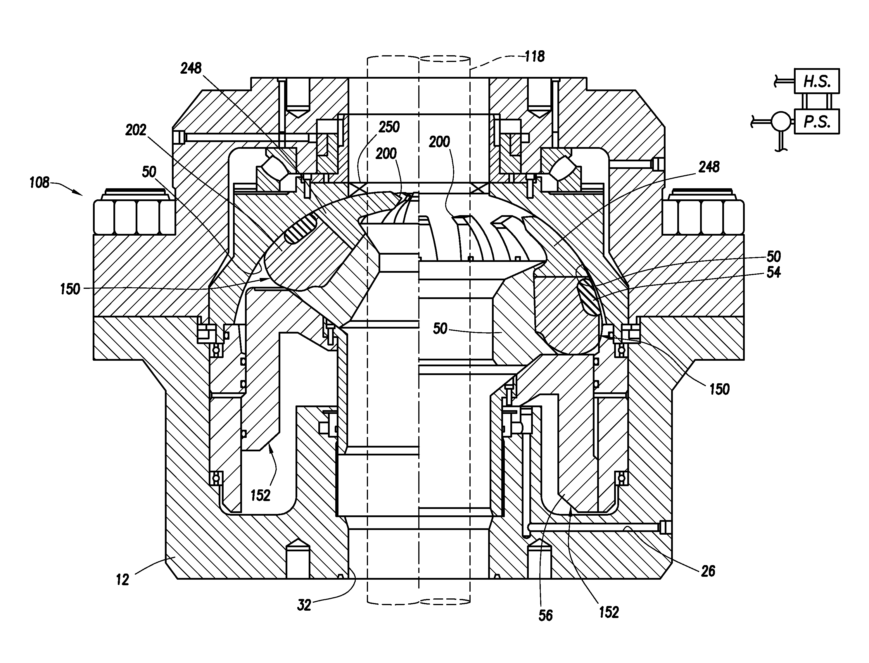
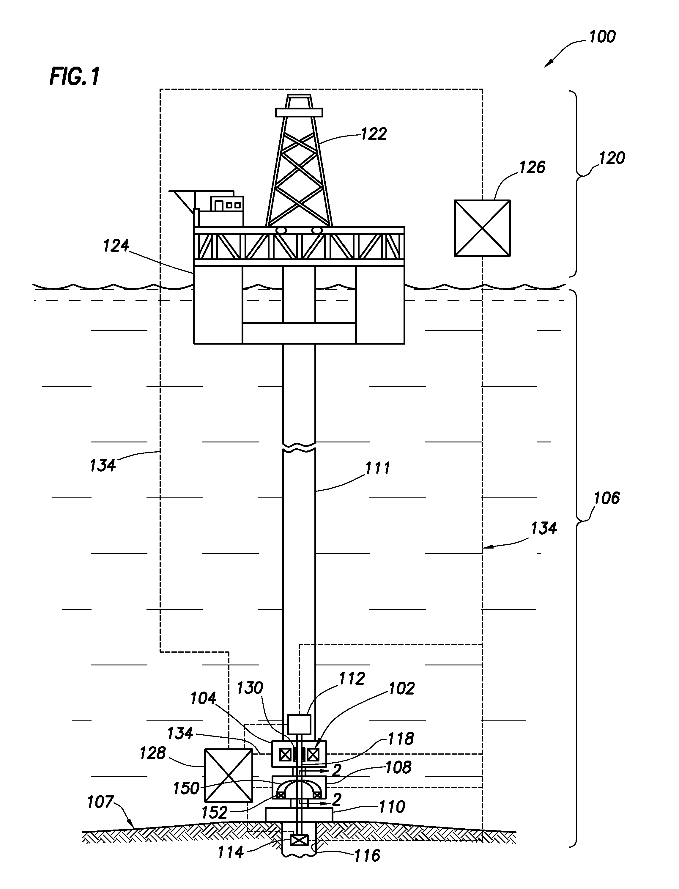
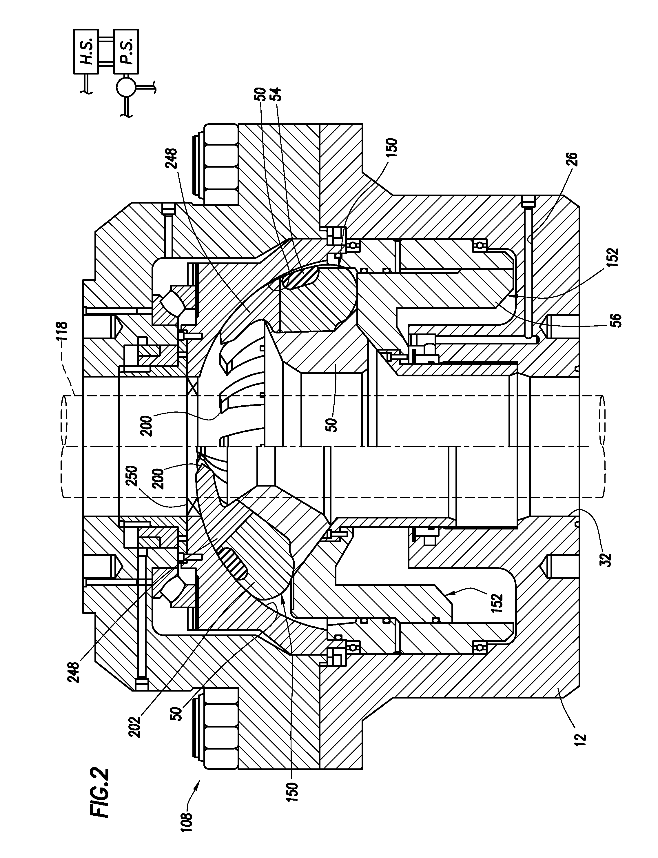
[0025]This application relates to a BOP and tubular severing system used to sever a tubular at a wellsite. The tubular may be, for example, a tubular that is run through the BOP during wellsite operations and / or other downhole tubular devices, such as pipes, certain downhole tools, casings, drill pipe, liner, coiled tubing, production tubing, wireline, slickline, or other tubular members positioned in the wellbore and associated components, such as drill collars, tool joints, drill bits, logging tools, packers, and the like, (referred to as ‘tubulars’ or ‘tubular strings’). The severing operation may allow the tubular to be removed from the BOP and / or the wellhead. Severing the tubular may be performed, for example...


PUM

PropertyMeasurementUnit
Angleaaaaaaaaaa

Abstract

The invention relates to techniques for severing a tubular. A blowout preventer is provided with a housing having a bore therethrough for receiving the tubular, an actuator positionable in the housing, and a plurality of cutting tools positionable in the housing and selectively movable into an actuated position with the actuator. Each of the cutting tools have a base supportable by the actuator and selectively movable thereby, and a cutting head supported by the base. The cutting head comprising a tip having a piecing point at an end thereof and at least one cutting surface. The piercing point pierces the tubular and the cutting surfaces taper away from the piercing point for cutting through the tubular whereby the cutting head passes through tubular.

Description

CROSS-REFERENCE TO RELATED APPLICATIONS[0001]This application is a continuation-in-part of U.S. Non-Provisional Application No. 12 / 883,469 filed on Sep. 16, 2010, which is a continuation of U.S. Non-Provisional Application No. 12 / 151,279 filed on May 5, 2008, which is now U.S. Pat. No. 7,814,979, which is a divisional of U.S. Non-Provisional Application No. 11 / 411,203 filed on Apr. 25, 2006, which is now U.S. Pat. No. 7,367,396, the entire contents of which are hereby incorporated by reference. This application also claims the benefit of U.S. Provisional Application No. 61 / 349,660 on May 28, 2010, U.S. Provisional Application No. 61 / 349,604 filed on May 28, 2010, U.S. Provisional Application No. 61 / 359,746 filed on Jun. 29, 2010, and U.S. Provisional Application No. 61 / 373,734 filed on Aug. 13, 2010, the entire contents of which are hereby incorporated by reference.BACKGROUND OF THE INVENTION[0002]1. Field of the Invention[0003]This present invention relates generally to techniques ...

Claims


Application Information

Patent Timeline
IPC IPC(8): E21B29/00E21B33/06
CPCE21B33/063Y10T83/0596
Inventor SPRINGETT, FRANK BENJAMINJOHNSON, CHRISTOPHER DALEPETERS, SHERN EUGENEENSLEY, ERIC TREVOR
Owner NAT OILWELL VARCO LP
Why Eureka
Try Eureka