Image forming apparatus and atmospheric air opening method

Inactive Publication Date: 2011-09-22
RICOH KK
View PDF10 Cites 8 Cited by
  • Summary
  • Abstract
  • Description
  • Claims
  • Application Information

AI Technical Summary

Benefits of technology

The present invention provides an image forming apparatus and an atmospheric air opening method, in which one or more of the above-described disadvantages are eliminated.
A preferred embodiment of the present invention provides an image forming apparatus and an atmospheric air opening method, in which a function that is intrinsically provided in a head unit such as a gap adjustment mechanism is used for performing an atmospheric air opening operation, so that the number of components is reduced and the apparatus is simplified.

Problems solved by technology

For example, as described in patent document 1, when air enters a supply path to the sub tank, a failure may occur in the negative pressure in the sub tank for a certain time period.
To attain the negative pressure, a predetermined amount of ink is ejected as described above, and therefore ink is wasted.
When a magnet valve or a solenoid is provided for selecting the atmospheric air opening operation as described above, the number of components increases, the control operation becomes complex, and the apparatus size becomes large.

Method used


Image

  • Image forming apparatus and atmospheric air opening method
  • Image forming apparatus and atmospheric air opening method
  • Image forming apparatus and atmospheric air opening method

Examples


first embodiment

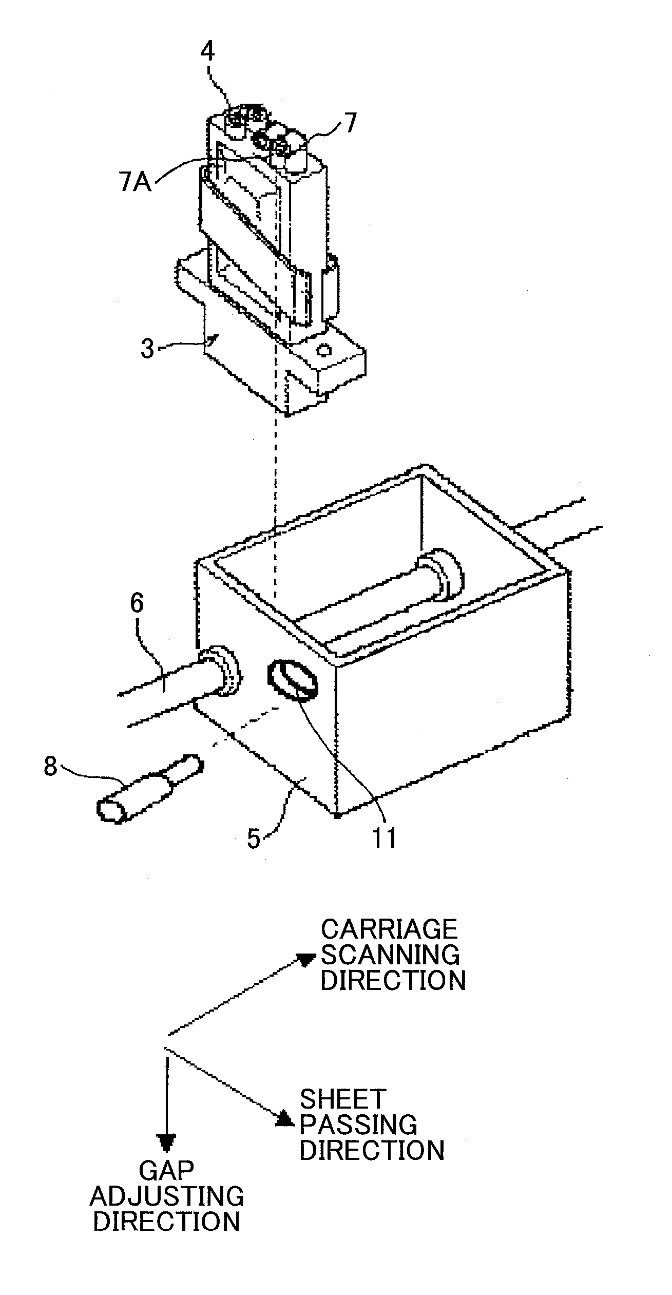
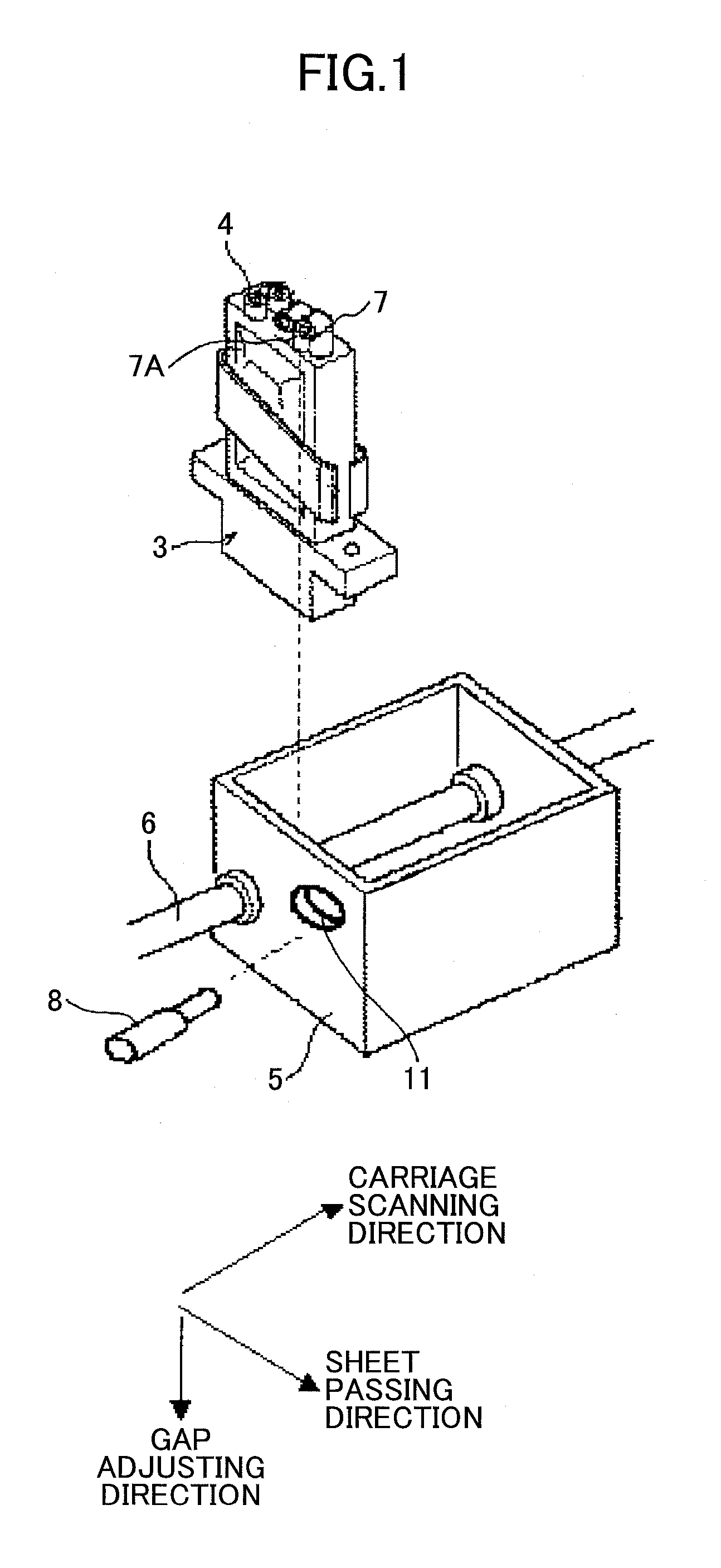
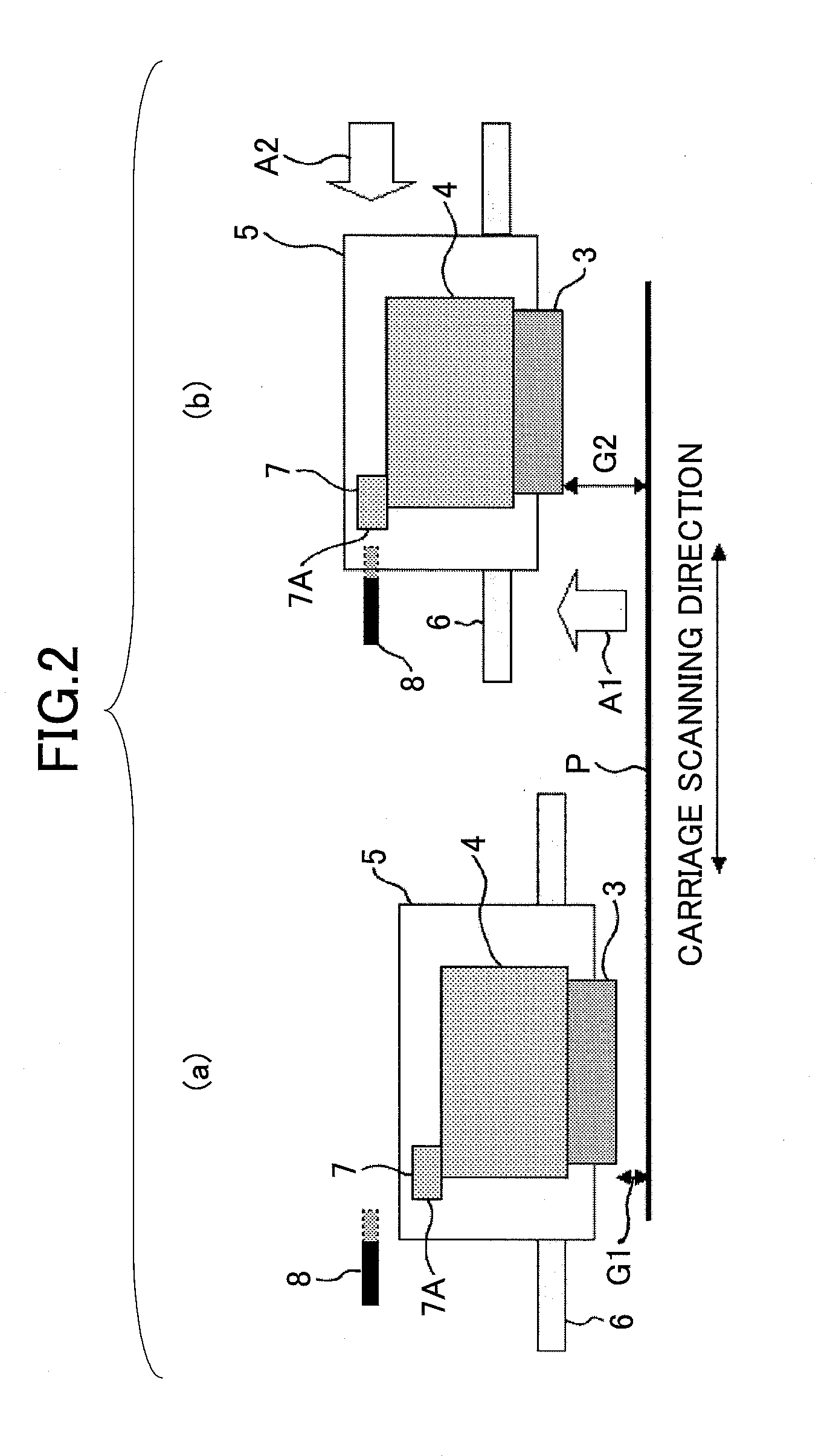
FIG. 1 is an exploded perspective view of an atmospheric air opening device according to a first embodiment of the present invention. FIG. 2 is for describing the operation of the atmospheric air opening device according to the first embodiment of the present invention.

As shown in FIG. 1, the atmospheric air opening device according to the present embodiment does not have the solenoid 9 provided for the atmospheric air opening device of the conventional example described with reference to FIG. 9. In the present embodiment, the pin hole 11 is formed in the side surface of the carriage 5, i.e., in the side surface perpendicular to the support shaft 6 of the carriage 5. The pin hole 11 is formed at a position such that the pin 8 can contact the atmospheric air opening mechanism 7 in the sub tank 4. The atmospheric air opening mechanism 7 is disposed in a direction such that an operation part 7A of the atmospheric air opening mechanism 7 faces the pin hole 11, i.e., in a direction paral...

second embodiment

FIG. 3 is an exploded perspective view of an atmospheric air opening device according to a second embodiment of the present invention. FIG. 4 is for describing the operation of the atmospheric air opening device according to the second embodiment of the present invention.

As shown in FIG. 3, the atmospheric air opening device according to the present embodiment does not have the solenoid 9 provided for the atmospheric air opening device of the conventional example described with reference to FIG. 9. Furthermore, the pin 8 is provided above the carriage 5, and the pin hole 11 is not provided. The other elements are configured similarly to the conventional example described with reference to FIG. 9.

In the present embodiment, as shown in FIG. 4, the pin 8 is provided at a predetermined position at an upper part of a path along which the operation part 7A of the atmospheric air opening mechanism 7 of the sub tank 4 moves. When the atmospheric air opening operation is to be performed, as ...

third embodiment

FIG. 5 is an exploded perspective view of an atmospheric air opening device according to a third embodiment of the present invention. FIG. 6 is for describing the operation of the atmospheric air opening device according to the third embodiment of the present invention.

As shown in FIG. 5, the atmospheric air opening device according to the present embodiment is different from the atmospheric air opening device according to the second embodiment of FIG. 3 in that the carriage 5 is lowered to perform the atmospheric air opening operation. The carriage 5 is lowered with the use of a mechanism for adjusting the head gap (hereinafter, a gap adjustment mechanism) 12. Specifically, the pin 8 is positioned below the carriage 5 (FIG. 6 (a)). When the gap adjustment mechanism 12 lowers the carriage 5, the tip of the pin 8 located below the carriage 5 presses the operation part 7A of the atmospheric air opening mechanism 7 of the sub tank 4 (FIG. 6 (b)), so that the atmospheric air opening ope...


PUM


Abstract

An image forming apparatus includes a sub tank that supplies a liquid to a head that ejects liquid droplets, the sub tank including a generating unit that generates a negative pressure inside the sub tank by expanding and contracting as the liquid is supplied to and ejected from the sub tank, and an opening mechanism that performs an opening operation of opening the sub tank to atmospheric air; a supply mechanism that supplies the liquid in a main tank to the sub tank; a carriage that moves in a main scanning direction above a sheet, the head being disposed in the carriage; a moving mechanism that changes a distance between the sheet and the head; and a control unit that causes the opening mechanism to perform the opening operation in conjunction with the moving mechanism changing the distance between the sheet and the ejecting head.

Description

BACKGROUND OF THE INVENTION1. Field of the InventionThe present invention relates to a liquid droplet ejecting type image forming apparatus and an atmospheric air opening method of a sub tank of a liquid droplet ejecting type recording head.2. Description of the Related ArtIn a liquid droplet ejecting type image forming apparatus, for example, an inkjet type image forming apparatus, a head unit is provided with a sub tank, and an amount of ink that has been consumed at a recording head is supplied to the sub tank from a main tank. For example, as described in patent document 1, when air enters a supply path to the sub tank, a failure may occur in the negative pressure in the sub tank for a certain time period. Therefore, a negative pressure recovery operation involving an atmospheric air opening operation is performed. The negative pressure recovery operation involving an atmospheric air opening operation is preferably performed only when air enters the supply path, because ink is c...

Claims


Application Information

Patent Timeline
IPC IPC(8): B41J2/175
CPCB41J2/1752B41J2/17509
Inventor NAKAMURA, DAISUKE
Owner RICOH KK
Why Eureka
Try Eureka