Sub Channel Generation for a Wireless Mesh Network

a wireless mesh network and sub-channel technology, applied in wireless communication, wireless communication, transmission path division, etc., can solve the problem that the simple fdma-based approach, as in the wifi mesh network, is not adequa

Inactive Publication Date: 2011-09-22
NOKIA SOLUTIONS & NETWORKS OY
View PDF15 Cites 82 Cited by
  • Summary
  • Abstract
  • Description
  • Claims
  • Application Information

AI Technical Summary

Problems solved by technology

This implies that the simple FDMA-based approach

Method used


Image

  • Sub Channel Generation for a Wireless Mesh Network
  • Sub Channel Generation for a Wireless Mesh Network
  • Sub Channel Generation for a Wireless Mesh Network

Examples


Embodiment Construction

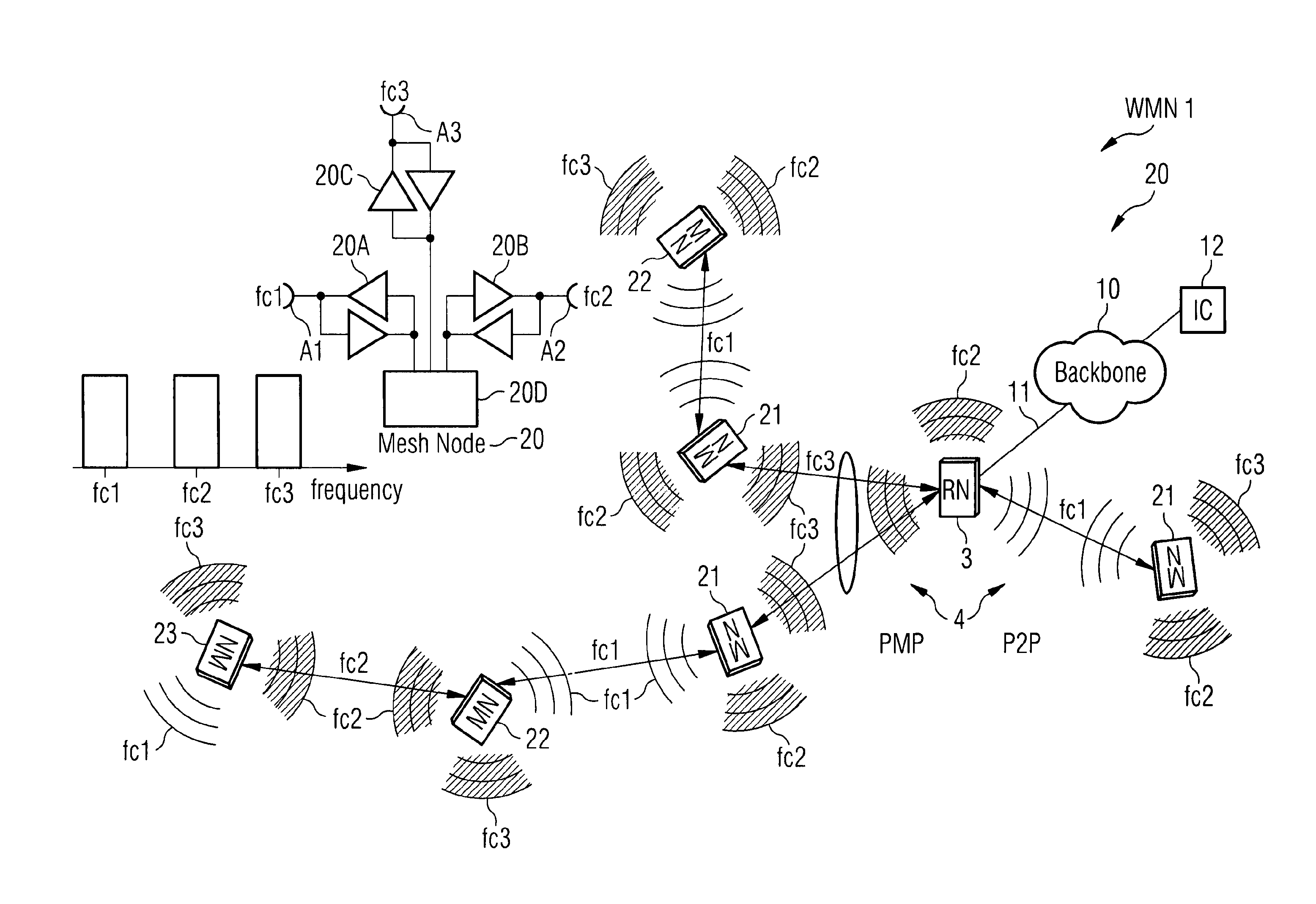
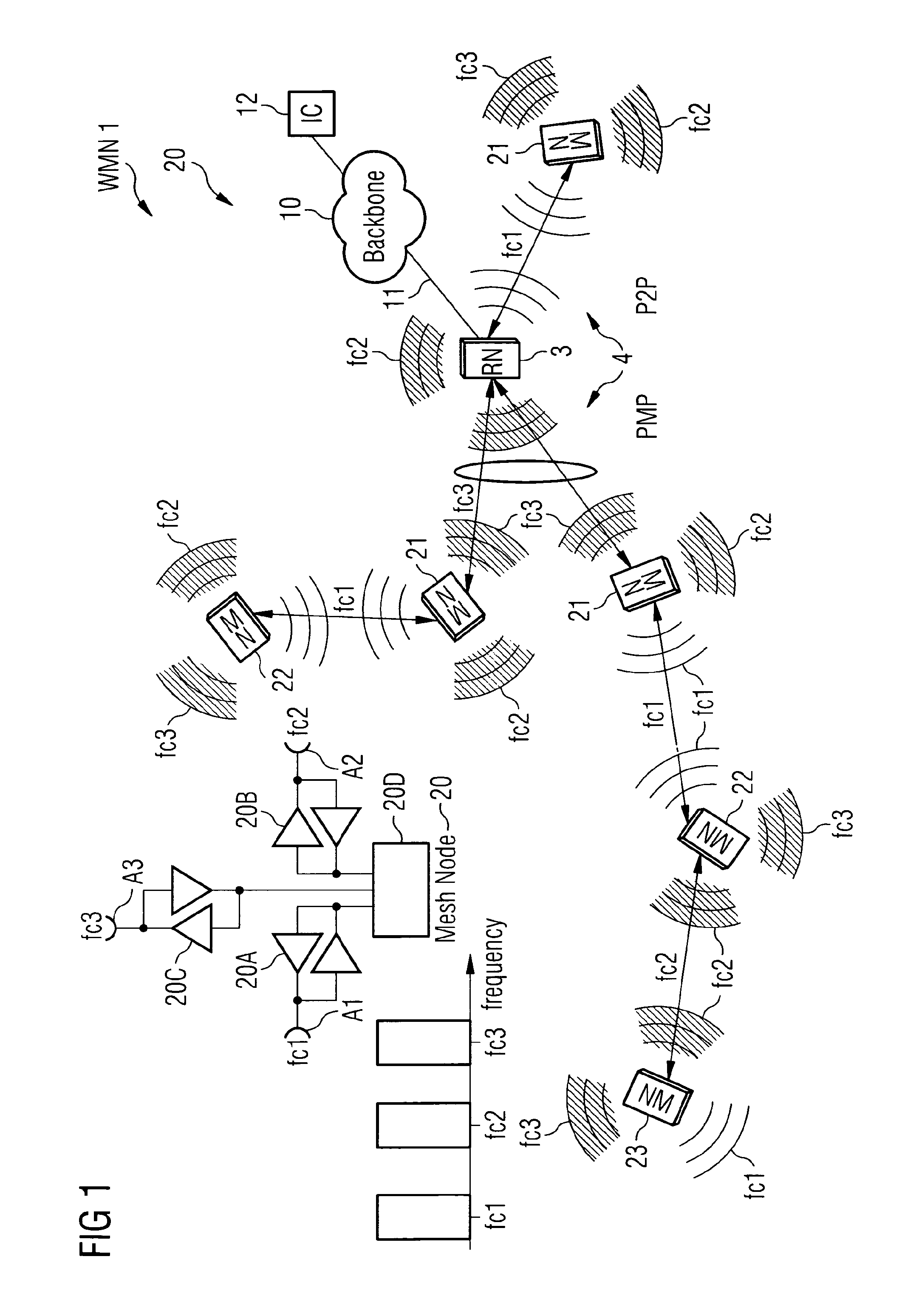
The exemplary embodiments of this invention relate to mesh infrastructure network technology and, more specifically, address and solve the problem of how to best allocate available radio resources to different transceivers of mesh nodes in the frequency, time and spatial domains in order to maximize system throughput and spectrum re-use across the mesh network. While described herein primarily in the context of wireless mesh networks, it should be appreciated that these embodiments have a wider scope and may also be employed with, as non-limiting examples, IEEE 802.16m and similar systems, as well the LTE system.

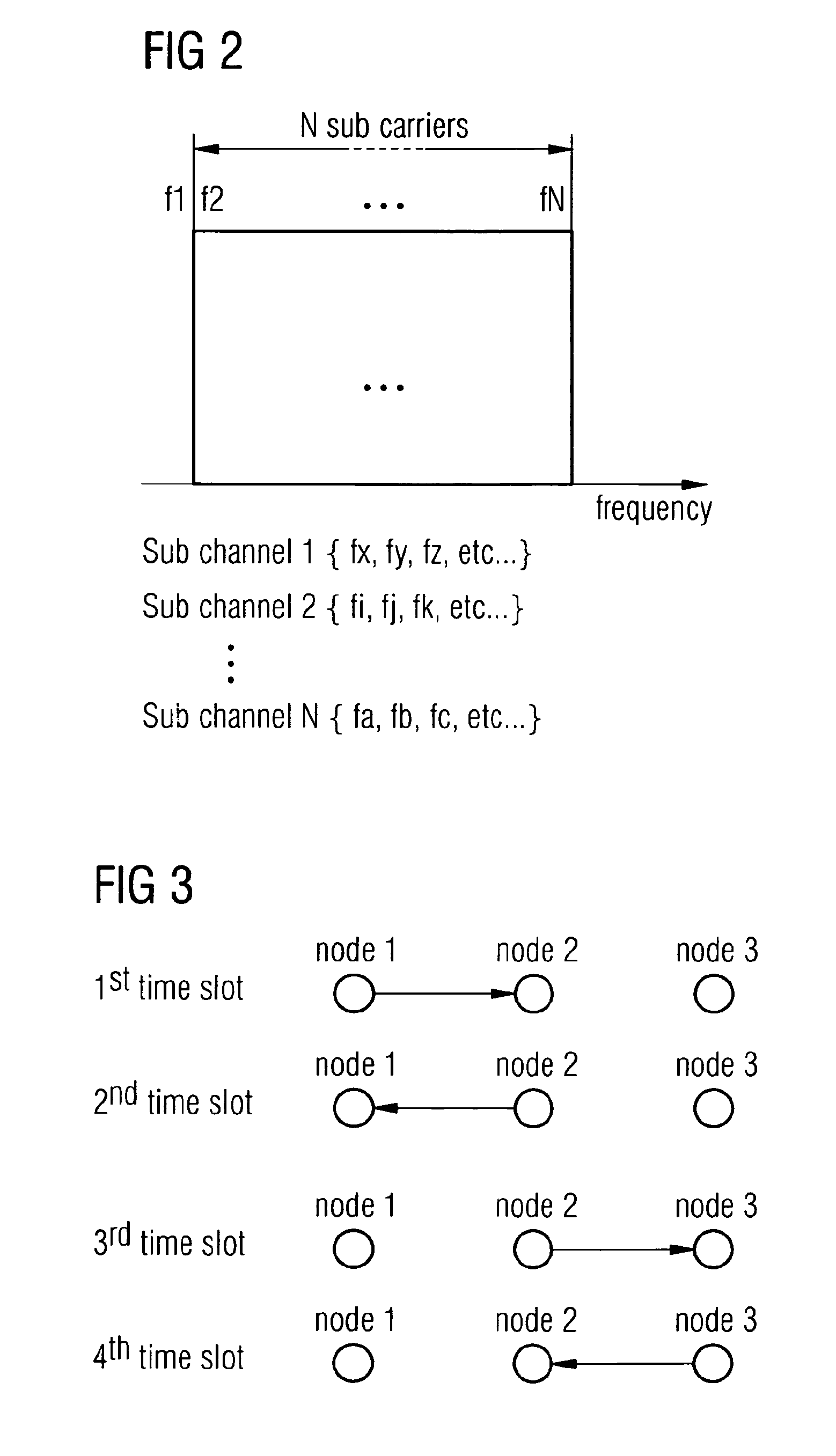
The exemplary embodiments address and solve the problem noted above with respect to spectrum allocation for wireless mesh networks, where it was noted that the simple FDMA-based approach, as in current WiFi mesh networks, will not be adequate. Instead, it would be desirable to design the system to use an OFDMA-based approach, where more flexible re-use of OFDM sub-carriers c...


PUM


Abstract

In accordance with an example embodiment of the present invention, there is at least a method, apparatus, and computer program for dividing an available bandwidth into a plurality of frequency bands or channels, dividing each of the plurality of frequency bands or channels into a plurality of orthogonal sub-carriers, organizing the sub-carriers into a plurality of sub-channels, and assigning at least some of the generated sub-channels to at least one corresponding radio link between parent and child nodes of a mesh network.

Description

TECHNICAL FIELDThe present application relates generally to wireless communication systems, methods, devices and computer programs and, more specifically, relate to wireless mesh node networks, including those capable of providing backhaul services.BACKGROUNDThis section is intended to provide a background or context to the invention that is recited in the claims. The description herein may include concepts that could be pursued, but are not necessarily ones that have been previously conceived or pursued. Therefore, unless otherwise indicated herein, what is described in this section is not prior art to the description and claims in this application and is not admitted to be prior art by inclusion in this section.Various abbreviations that appear in the specification and / or in the drawing figures are defined as follows:BTS base transceiver stationCDMA code division multiple accessCP cyclic prefixDL downlinkDVB digital video broadcastFDD frequency division duplexFDMA frequency divisi...

Claims


Application Information

Patent Timeline
IPC IPC(8): H04W72/04
CPCH04L5/0007H04L5/003H04L5/0067H04W72/00H04W72/04H04W84/18H04L1/00H04L27/2601H04L2001/0097
Inventor HONKASALO, ZHI-CHUNZHAO, ZHU YAN
Owner NOKIA SOLUTIONS & NETWORKS OY
Why Eureka
Try Eureka