Composite contact assembly having lower contact with contact engaging points offset from each other

a technology of contact assembly and offset point, which is applied in the direction of coupling contact member, coupling device connection, instrument, etc., can solve the problems of reducing the retaining force and affecting the electrical connection between the upper contact and the lower conta

Active Publication Date: 2011-09-22
HON HAI PRECISION IND CO LTD
View PDF4 Cites 19 Cited by
  • Summary
  • Abstract
  • Description
  • Claims
  • Application Information

AI Technical Summary

Benefits of technology

[0008]Accordingly, an object of the present invention is to provide an electrical contact assembly having improved arrangements between an upper contact and a lower contact thereof; so as to ensure reliable electrical connection between the lower contact and a mating upper contact.

Problems solved by technology

However, the retaining force will be reduced if the contact assembly is used in some worse application and the electrical connection between the upper contact and lower contact will be affected.

Method used


Image

  • Composite contact assembly having lower contact with contact engaging points offset from each other
  • Composite contact assembly having lower contact with contact engaging points offset from each other
  • Composite contact assembly having lower contact with contact engaging points offset from each other

Examples


Embodiment Construction

[0014]Reference will now be made to the drawings to describe the present invention in detail.

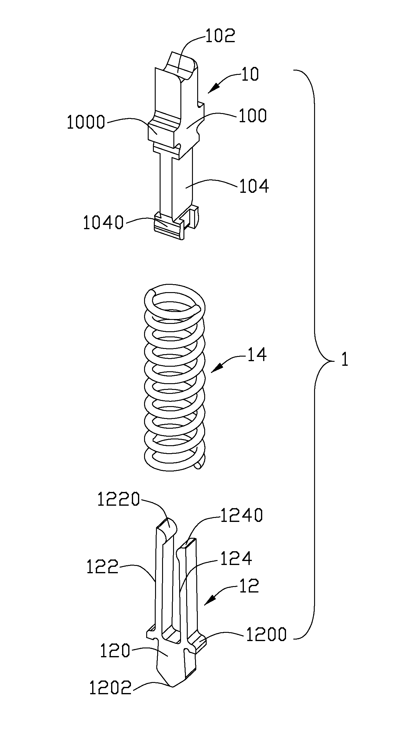
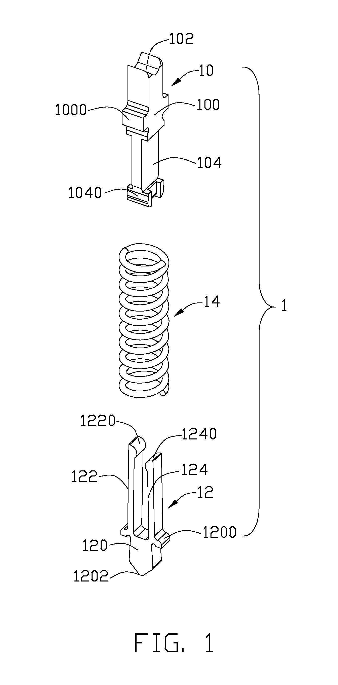
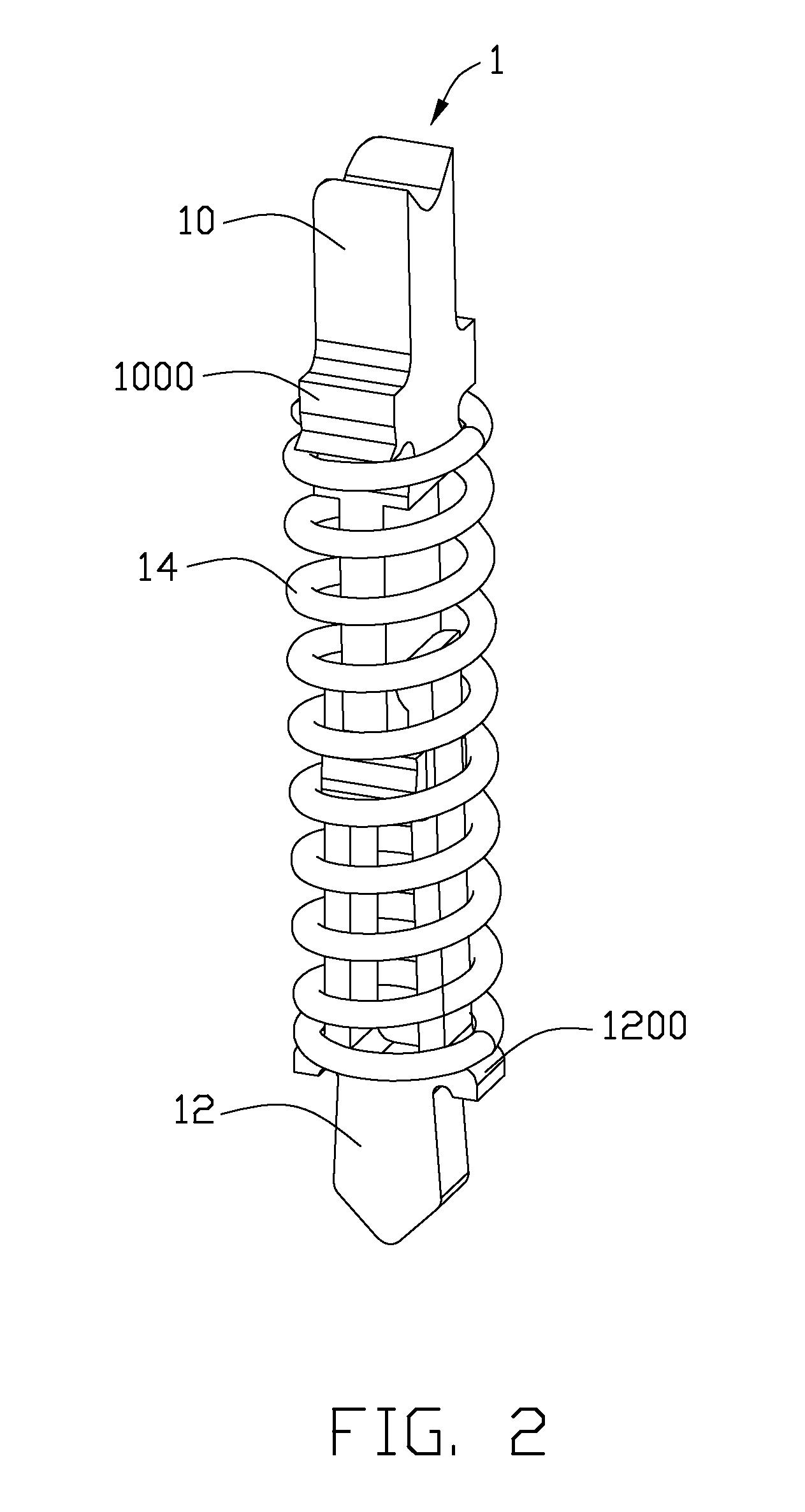
[0015]Referring to FIGS. 1-3, the electrical contact assembly 1 is used to electrically connecting a Central Processing Unit (CPU) (not shown) with a Printed Circuit Board (PCB) (not shown). The electrical contact assembly 1 comprises an upper contact 10, a lower contact 12 and a spring 14 located between the upper contact 10 and the lower contact 12.

[0016]The upper contact 10 comprises a main body 100, a first contacting portion 102 extending upwardly from a top end of the main body 100 for engaging with the CPU, and a lower mating end 104 extending downwardly from a lower end of the main body 100. The main body 100 defines a pair of first keeping portion 1000 at opposite edges thereof for positioning the spring 14 jointly with a second keeping portion 1200 formed on the lower contact 12. The lower mating end 104 defines a pair of hooks 1040 formed on opposite edges thereof. The hooks 1040 ...


PUM


Abstract

An electrical contact assembly electrical contact assembly comprises upper contact having a lower mating end at a lower end thereof, a lower contact having a base portion and a pair of mating beams extending vertically from the base portion for a length respectively and for engaging with the lower mating end of the upper contact, and a spring located between the upper contact and the lower contact. A channel is defined between the mating beams and providing a space to allow movement of the lower mating end. The pair of mating end has unequal lengths for providing unequal torque on the lower mating end, thus ensuring reliable electrical connection between the upper contact and lower contact even under worse circumstance.

Description

BACKGROUND OF THE INVENTION[0001]1. Field of the Invention[0002]The present invention relates to an electrical contact assembly, and more particularly, to a composite contact assembly having lower contact with contact engaging points offset from each other thus establishing reliable electrical connection between the lower contact and a mating upper contact.[0003]2. Description of the Prior Art[0004]Burn-in Socket is widely used for testing an IC package, so as to detect performance of the IC package and distinguish defective IC packages. A typical Burn-in Socket generally comprises an insulative housing having a number of electrical contact assemblies received therein. The electrical contact assembly generally comprises an upper contact, a lower contact and a spring between the upper contact and the lower contact. The upper contact comprises a flat base portion with a first contact portion at the top end. The lower contact comprises a flat body portion and a pair of arm portions ext...

Claims


Application Information

Patent Timeline
Patent Type & Authority Applications(United States)
IPC IPC(8): H01R13/24H01R4/28
CPCG01R1/0466H01R2201/20H01R13/2421H01R12/714
Inventor HSU, HSIU-YUANLIN, CHUN-FUHSIAO, SHIH-WEICHEN, KE-HAO
Owner HON HAI PRECISION IND CO LTD
Why Eureka
Try Eureka