
Fast warm-up and instant light energy saving lamp assembly

a lamp assembly, fast technology, applied in the direction of transit-tube circuit elements, manufacturing tools, cathode-ray/electron beam tube circuit elements, etc., can solve the problems of reducing the run-up period, not providing instant light feature, not providing efficient and effective ways of warming up mercury sources, etc., to achieve fast warm-up

Inactive Publication Date: 2011-09-29
GENERAL ELECTRIC CO
View PDF8 Cites 9 Cited by
  • Summary
  • Abstract
  • Description
  • Claims
  • Application Information

AI Technical Summary

Benefits of technology

[0008]A lamp assembly of the present disclosure provides for fast warm-up, instant light, and is also an energy saving lamp that advantageously uses two light sources in a single outer bulb.
[0015]A primary benefit of the present disclosure is the ability to provide instant with an energy saving lamp assembly that has a fast warm-up.
[0016]Another benefit resides in that both light sources are located within a common outer bulb to achieve the shortest warm-up period by reducing wasted heat to the environment.
[0017]Still another benefit is associated with a simple construction that is easy to manufacture and is low cost.

Problems solved by technology

In this way, the run-up period is reduced, although this proposed solution does not provide an instant light feature.
Although it has been suggested to simultaneously turn on both lamps in order to result in instant light from the incandescent lamp, and then subsequently terminate or switch off the incandescent lamp, these known arrangements do not provide an efficient and effective manner for warming up the mercury source.
This arrangement does not provide an accurate assessment of the actual thermal conditions of the discharge vessel.
Further, locating a thermally sensitive element in a ballast compartment is potentially impacted by temperature variations caused by different illumination positions of the lamp e.g. vertically upright or inverted.
As a result, the thermally sensitive element does not provide an accurate representation of the heat conditions.
Although the thermal switch associated with this arrangement aids in starting of the fluorescent lamp in low temperature, ambient conditions, it does not improve run-up of the lamp assembly.
Unfortunately, due to the SCR, the RMS value of the input power is about 70% of the nominal and results in a specialized incandescent lamp.

Method used


Image

  • Fast warm-up and instant light energy saving lamp assembly
  • Fast warm-up and instant light energy saving lamp assembly
  • Fast warm-up and instant light energy saving lamp assembly

Examples


Embodiment Construction

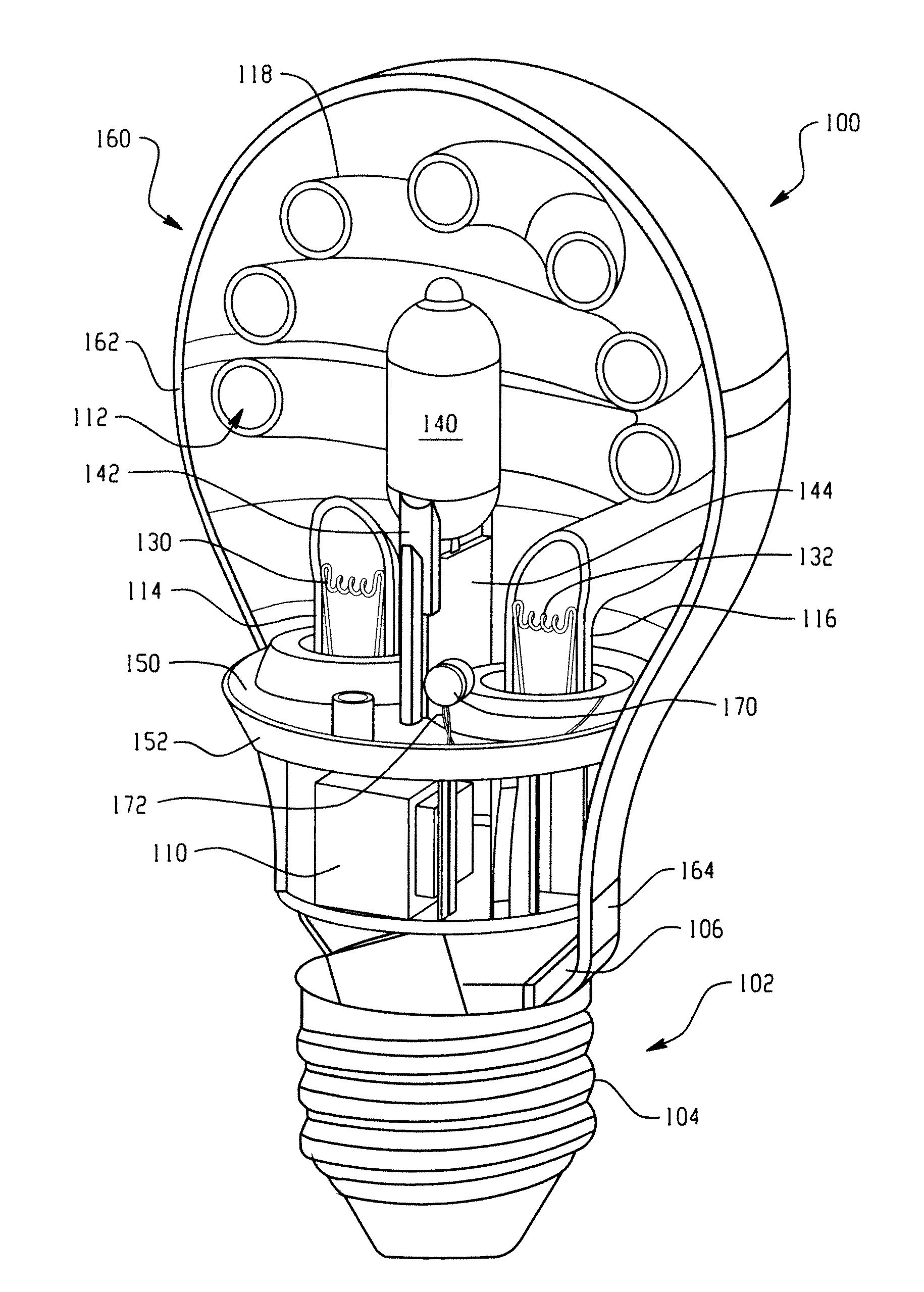
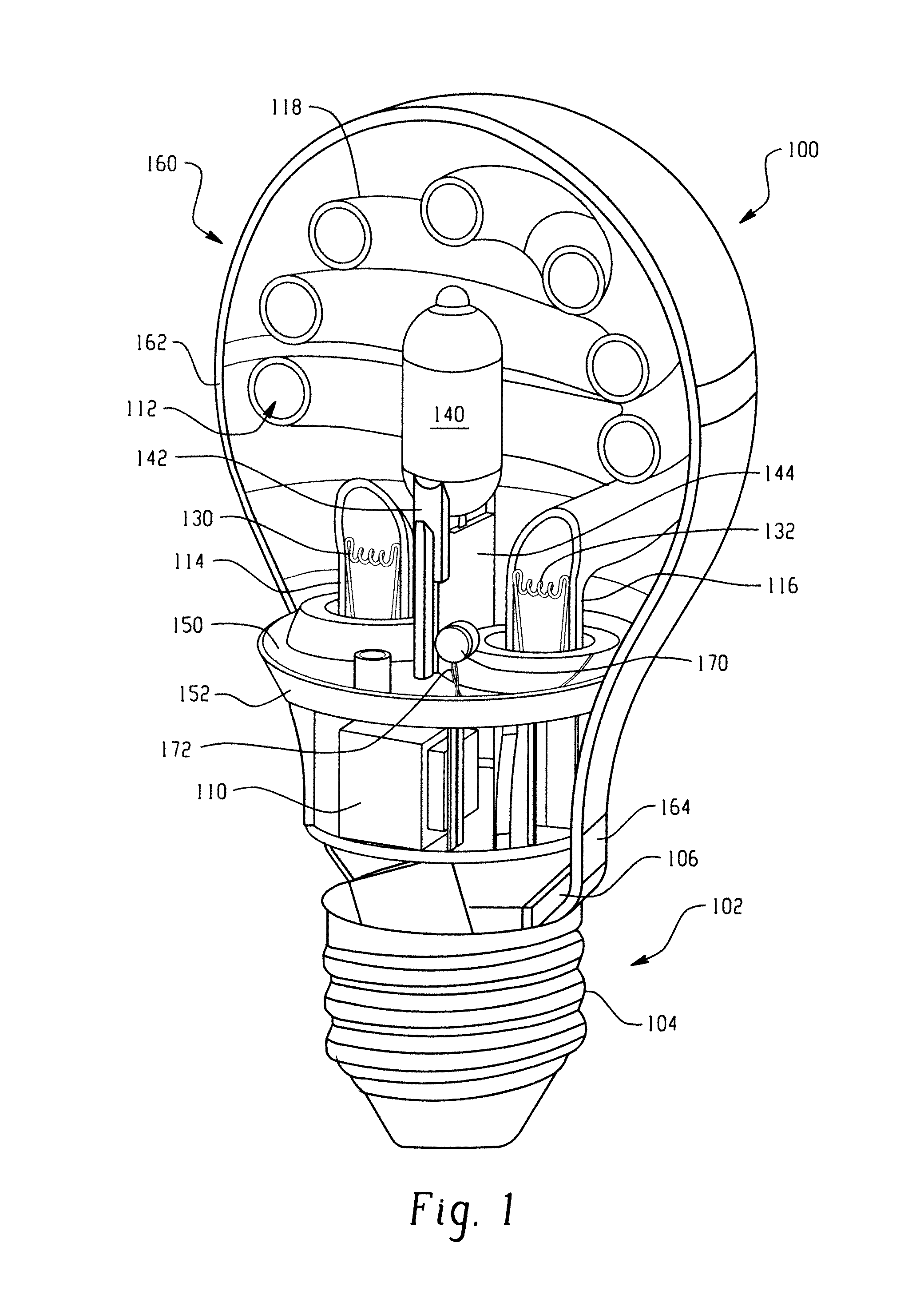
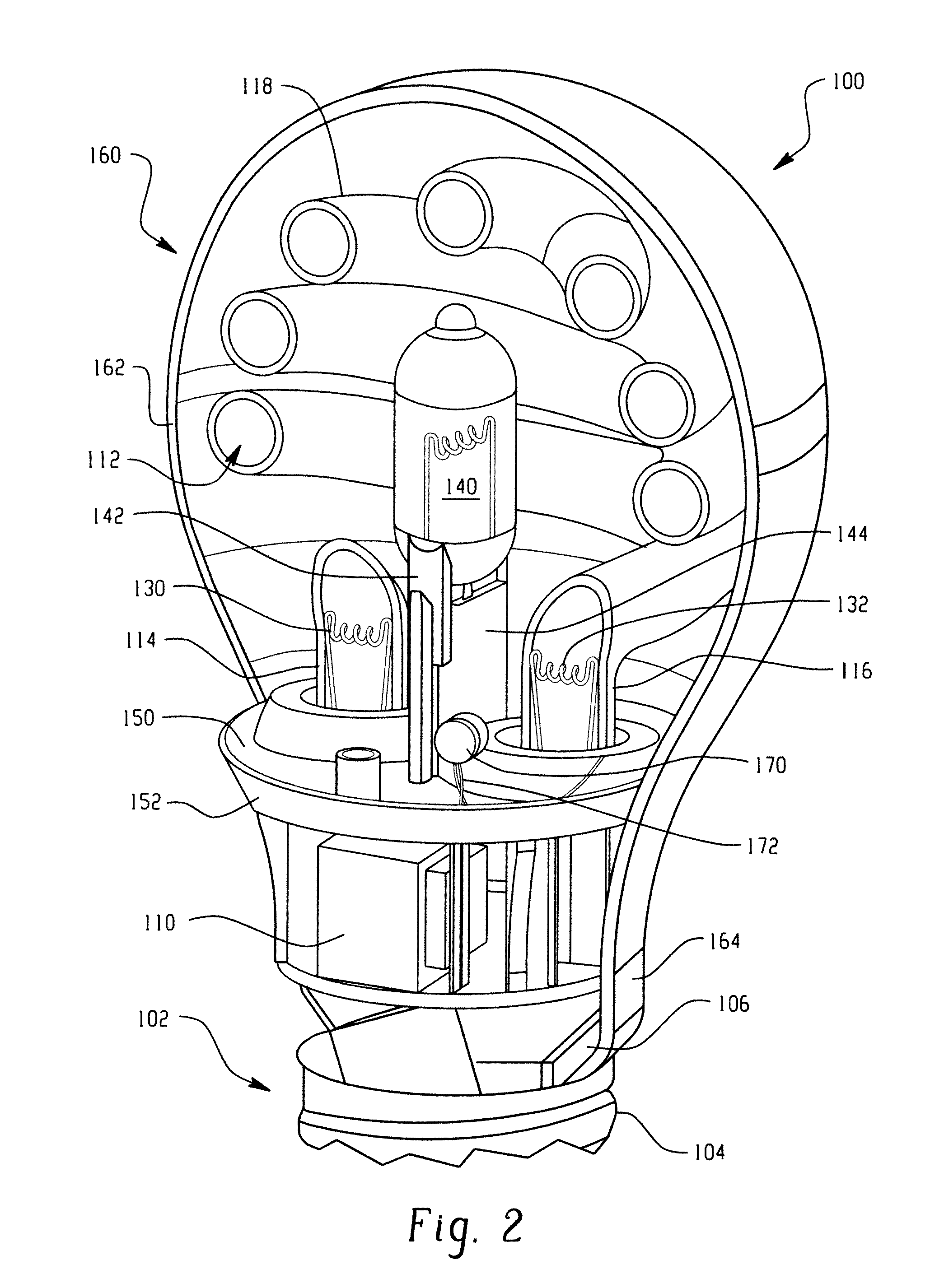
[0022]FIGS. 1 and 2 show a lamp assembly, and more particularly a compact fluorescent lamp assembly 100 that is generally referred to as an energy saving lamp or light source that advantageously provides instant light and fast warm-up. A lamp base 102 includes a mechanical and electrical arrangement for receipt in an associated lamp socket (not shown) to mechanically support the lamp assembly 100 and provide power to operate the lamp assembly. More particularly, and without need to be limiting, a conventional Edison-base 102 is shown that includes a conductive, threaded metal shell 104 for threaded receipt in an associated lamp socket, and typically includes an electrical eyelet or second contact (not shown) spaced from the threaded shell 104 by insulating material at the lower end of the lamp assembly. This arrangement provides a two lead arrangement for establishing electrical contact associated with the lamp socket in a manner generally known in the art.

[0023]At least a portion o...


PUM

PropertyMeasurementUnit
fluorescentaaaaaaaaaa
temperatureaaaaaaaaaa
volumeaaaaaaaaaa

Abstract

A lamp assembly provides both instant light through use of an incandescent / halogen lamp source and an energy saving type light provided by a compact fluorescent lamp source. Both light sources are enclosed within a common envelope or outer bulb. The sensor member monitors a temperature of the cathode and mercury reservoir of the compact fluorescent lamp source in order to determine when to terminate power to the incandescent lamp source.

Description

BACKGROUND OF THE DISCLOSURE[0001]This disclosure is directed to a lamp assembly, and particularly a lamp assembly that provides energy savings. More specifically, the lamp assembly also provides for instant light and fast warm-up.[0002]A number of different solutions currently exist to improve run-up behavior, i.e., reducing the time to full light associated with starting or igniting fluorescent lamps. By way of example only, long-life compact fluorescent lamps need approximately 0.5 to 1.5 seconds to preheat the cathodes or electrodes before starting. Before preheating is complete, there is no light emission from the lamp. Once the arc discharge is initiated, the compact fluorescent lamp (CFL) still requires an additional approximately 20 to 120 seconds or more to reach full light output.[0003]Prior arrangements have attempted to reduce the run-up time of a CFL that uses amalgam mercury dosing by incorporating an auxiliary amalgam close to one of the electrodes in the lamp. As a r...

Claims


Application Information

Patent Timeline
Patent Type & Authority Applications(United States)
IPC IPC(8): H01K1/62B23P17/04
CPCH05B35/00Y10T29/49826Y02B20/19Y02B20/00
Inventor WURSCHING, ISTVANFULOP, JOZSEFPAPP, FERENCLUKACS, SANDORVIGH, PETER
Owner GENERAL ELECTRIC CO
Learn More