
Positioning system calibration

Active Publication Date: 2011-09-29
XSENS HLDG
View PDF4 Cites 10 Cited by
  • Summary
  • Abstract
  • Description
  • Claims
  • Application Information

AI Technical Summary

Benefits of technology

The invention provides a system and apparatus for calibrating an RF positioning system that eliminates or minimizes the above mentioned drawbacks. In an embodiment of the invention, means are provided for automated calibration of an RF positioning system based on simple user or a priori input that does not require accuracy. Thus, the disclosed calibration means enables nomadic deployment of RF positioning systems by enabling fast and easy calibration and re-calibration of the system based on in-use data to correct for changes in the system during use. Furthermore, in an embodiment of the invention, means are provided for direct feedback of calibration accuracy to the user. In a further embodiment of the invention, the full use of a RF positioning system is enabled by obtaining optimal accuracy even at the outskirts of the tracking volume and by providing optimal accuracy for a given number of receivers.
The disclosed method allows complete calibration of an RF positioning system without the need for manual surveying or measurement, in that the provided method determines both the receiver positions and their clock parameters. The disclosed method thus removes the need for the labor intensive, error prone and time consuming process of surveying the receiver positions and allows for flexible and mobile setups with a very fast setup-time. This disclosure focuses on time-based methods (where position is inferred from signal travel time), but this is just by way of example, and the described principles are not limited to such systems.

Problems solved by technology

Numerous internally and externally referenced systems have been used for such purposes, but there are still many issues to solve in terms of occlusion, lag, resolution, economical feasibility of the required installation, and so on.
The surveying of the receiver positions and calibration transmitter positions is typically a labor intensive and time consuming process, prone to measurement errors, and as such is only feasible for permanent setups, typically in logistics applications, where the setup is part of the permanent ICT infrastructure of a building.
However, such estimated receiver positions, as well as any receiver position errors in surveying can have a disproportionate impact on overall system accuracy, depending on the receiver geometry and the transmitter position in-use.
Furthermore, an often overlooked fact is that spatial inaccuracy in the position of the receivers and / or calibration transmitters placed in the measurement volume directly causes errors in the clock offset calibration of the receivers, i.e. spatial and temporal calibration parameters are closely linked and can cause non-intuitive errors in the system performance as a whole.
However, current calibration methods have no means of making errors caused by erroneous calibration known to the user.
Hence the user may only become aware of a need for improved calibration by noticing inadequate system performance during use.
Many applications demand easy and fast deployment in the field in un-controlled environments, such as military / firefighters / police and first responder personnel tracking applications, and such applications are currently hampered by inadequate calibration means.
Notably, since the time calibration accuracy required is so high (in the order of pico seconds) even exchanging cables in the system or movement of the cables used for time synchronization of the receivers can cause a need for re-calibration.

Method used

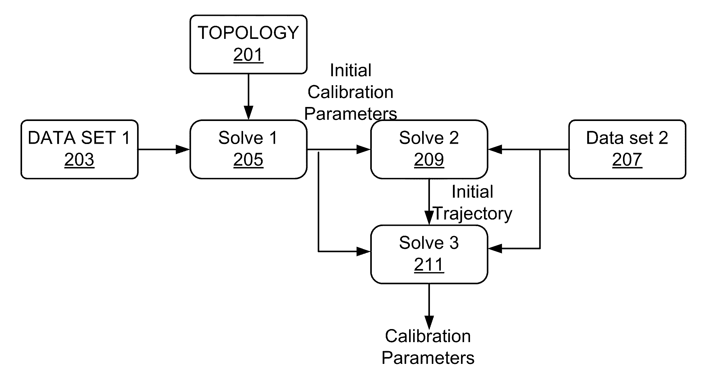
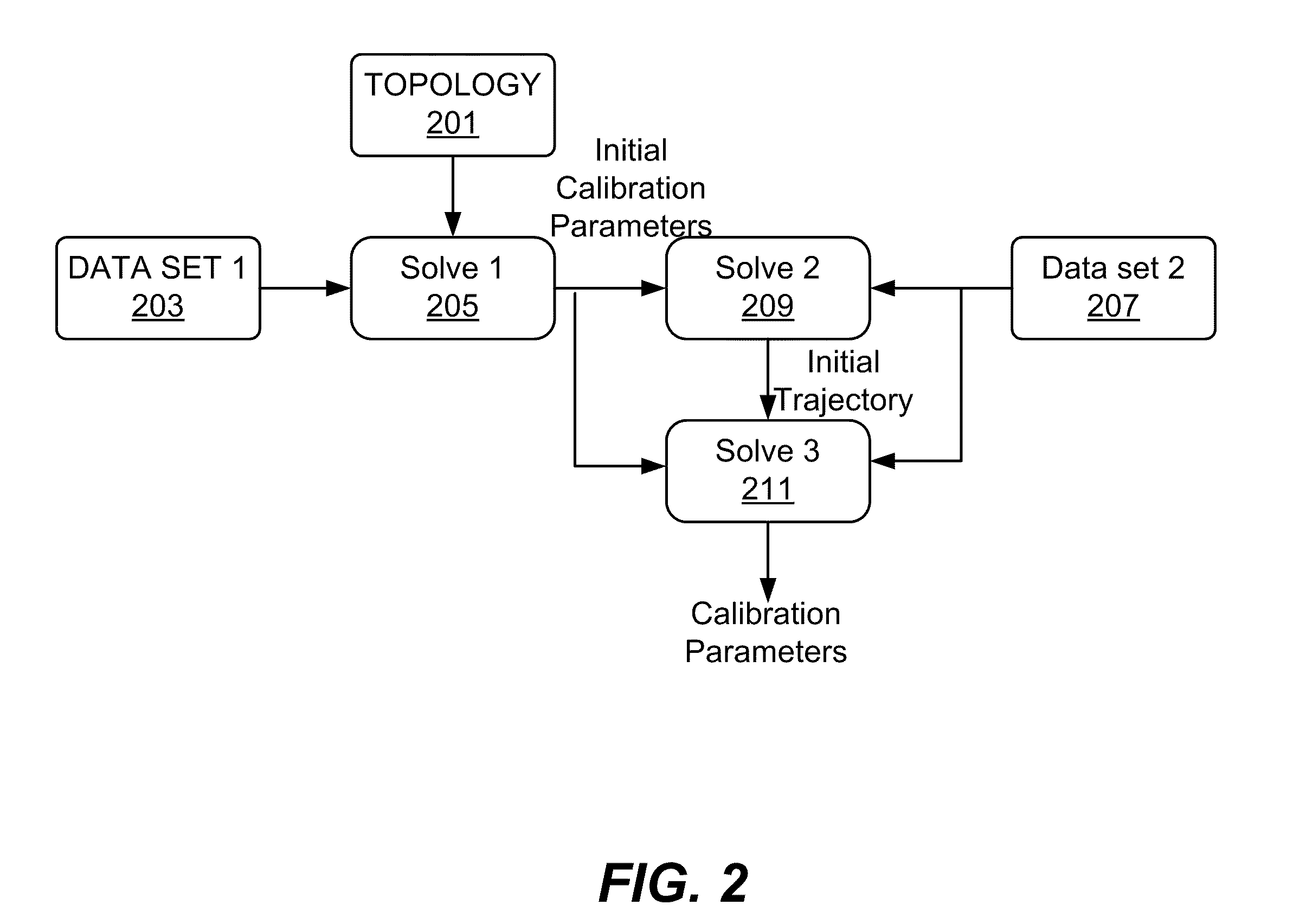

Image

  • Positioning system calibration
  • Positioning system calibration
  • Positioning system calibration

Examples


Embodiment Construction

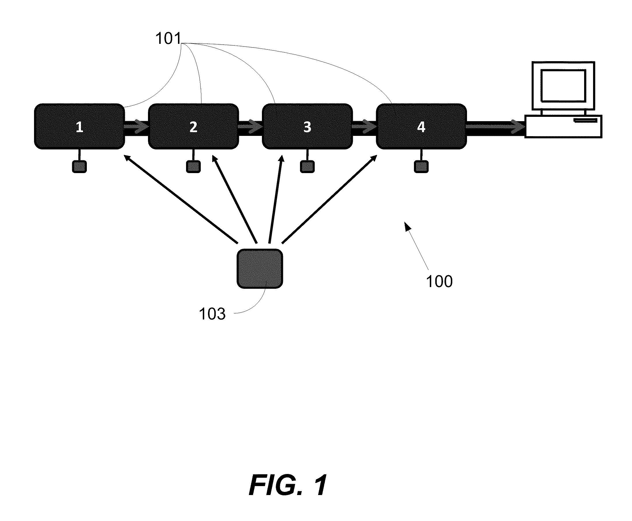
Prior to discussing specific techniques and implementations, an exemplary RF positioning system, for use as a basis of discussion, will be described by reference to FIG. 1. The illustrated UWB system 100 consists of a network of synchronized and stationary (rigidly fixed, mounted) receivers 101, all taking very precise time-of-arrival (TOA) measurements of signals originating from a transmitter 103. That is, the TOA measurement γmnk is the time (according to its local clock) where receiver m receives the k-th pulse from transmitter n. It can be modeled as

  (1)

Where is the time-of-transmission of the k-th pulse from transmitter n, is the position of transmitter of the k-th pulse from transmitter n, rm is the position of the m-th receiver and Δτm is the clock-offset of the m-th receiver. δmnk≧0 is a possibly nonzero delay due to non line-of-sight conditions or multipath and emnk is Gaussian noise.

Without loss of generality, all quantities in equation (1) are expressed in meters. Thi...


PUM


Abstract

The described principles provide a method and system for calibrating an UWB RF positioning system. Means for automated calibration of the UWB RF positioning system allow calibration based on simple user input that does not require accuracy. Thus, the disclosed calibration means enables nomadic deployment of UWB RF positioning systems by enabling fast and easy calibration and re-calibration of the system based on in-use data to correct for changes in the system during use. Furthermore, in an embodiment of the invention, means are provided for direct feedback of calibration accuracy to the user. In a further embodiment of the invention, the full use of a UWB positioning system is enabled by obtaining optimal accuracy even at the outskirts of the tracking volume and by providing optimal accuracy for a given number of receivers.

Description

BACKGROUND OF THE INVENTIONIn a number of industries and endeavors, it is important to be able to track the location of an object. For example, a human body may be tracked for purposes of animation or sports analysis, or an item of equipment may be tracked for security or logistics purposes. Numerous internally and externally referenced systems have been used for such purposes, but there are still many issues to solve in terms of occlusion, lag, resolution, economical feasibility of the required installation, and so on.Ultra-wideband (UWB) RF positioning is a relatively new positioning technology that is especially useful for indoor applications. Among the more mature applications of UWB are the so-called asset tracking systems in, e.g., health-care or manufacturing. Commercially available systems may consist of a network of time synchronized UWB receivers which track a large number of small, battery powered and inexpensive UWB transmitters. Typically the time synchronization is imp...

Claims


Application Information

Patent Timeline
IPC IPC(8): G01S7/40
CPCG01S5/021G01S2013/466G01S5/0294
Inventor HOL, JEROEN D.LUINGE, HENDRIK JOHANNESSLYCKE, PER JOHAN
Owner XSENS HLDG
Learn More