Image processing method, image processing apparatus, inkjet image forming apparatus and correction coefficient data generating method

Active Publication Date: 2011-09-29
FUJIFILM CORP
View PDF1 Cites 42 Cited by
  • Summary
  • Abstract
  • Description
  • Claims
  • Application Information

AI Technical Summary

Benefits of technology

[0051]According to the present invention, the correction coefficients for the respective nozzles are determined in accordance with landing interference patterns which take account of effects of landing interference between droplets ejected by other nozzl

Problems solved by technology

When an inkjet head of this kind is installed in a printing apparatus, it is necessary to adjust the angle and position of installation of the head, but there are limits on the mechanical adjustment precision.
Furthermore, in addition to the problem of depositing position error caused by the adjustment accuracy described above, when starting to use the inkjet head, nozzles which are in a state of ejection failure also arise due to blockages, failures, and the like.
When general ejection failure correction technology is used in a head having depositing position errors and ejected droplet volume errors, if the same correction coefficient is used for all of the ejection failure nozzles, then correction may be excessive or insufficient, depending on the state of arrangement of the nozzles, and black stripes or white stripes may become visible on the surface of the paper.
However, in the ejection failure correction technology of the related art, the physical conditions which are considered in particular as the dominant factors are mainly limited to two items only, namely, the depositing position and the dot diameter (which has a correlation with the volume of the ejection droplet) of the ejected liquid.
The image formation process by an inkjet head cannot be described fully on the basis of these two physical conditions alone, and there

Method used


Image

  • Image processing method, image processing apparatus, inkjet image forming apparatus and correction coefficient data generating method
  • Image processing method, image processing apparatus, inkjet image forming apparatus and correction coefficient data generating method
  • Image processing method, image processing apparatus, inkjet image forming apparatus and correction coefficient data generating method

Examples


first embodiment

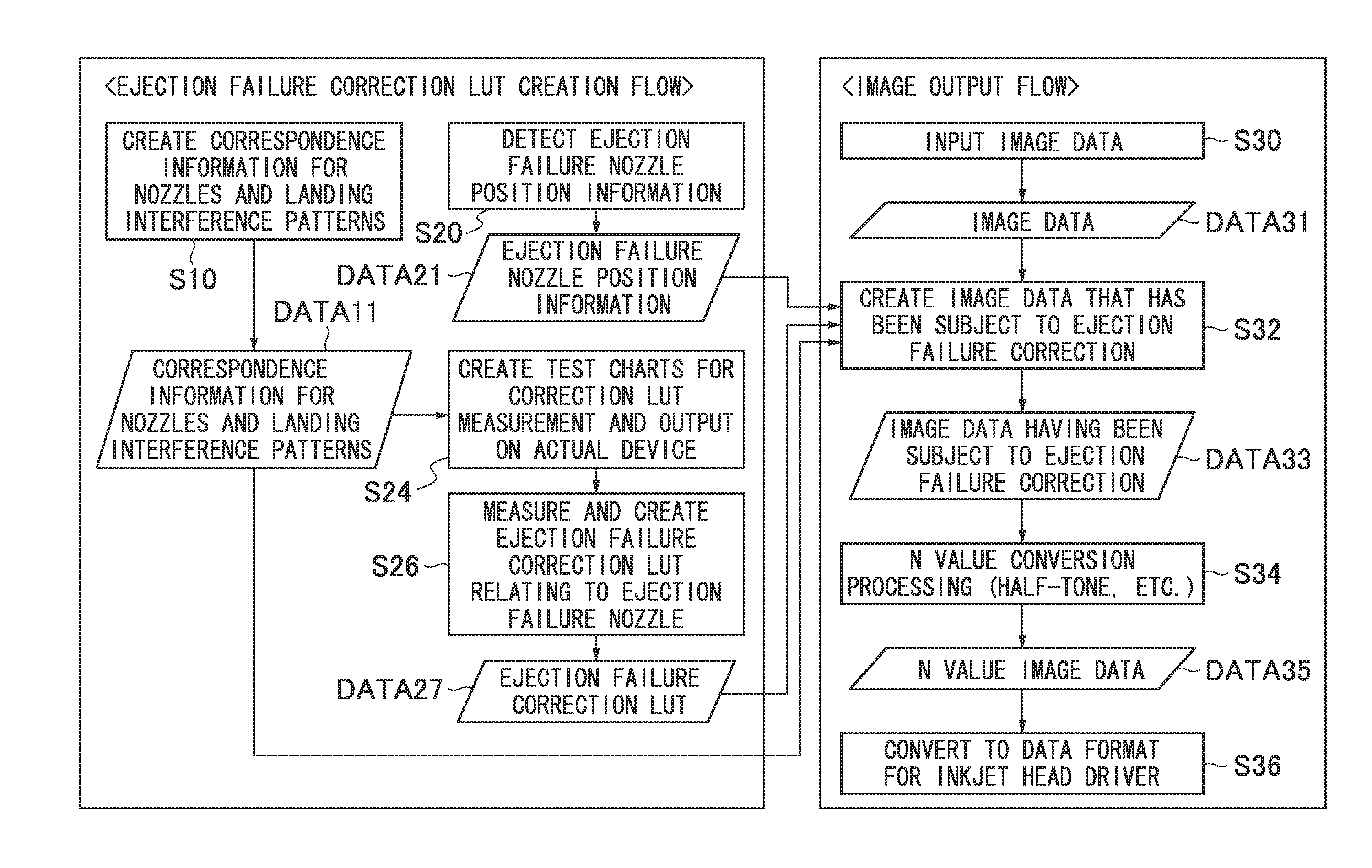
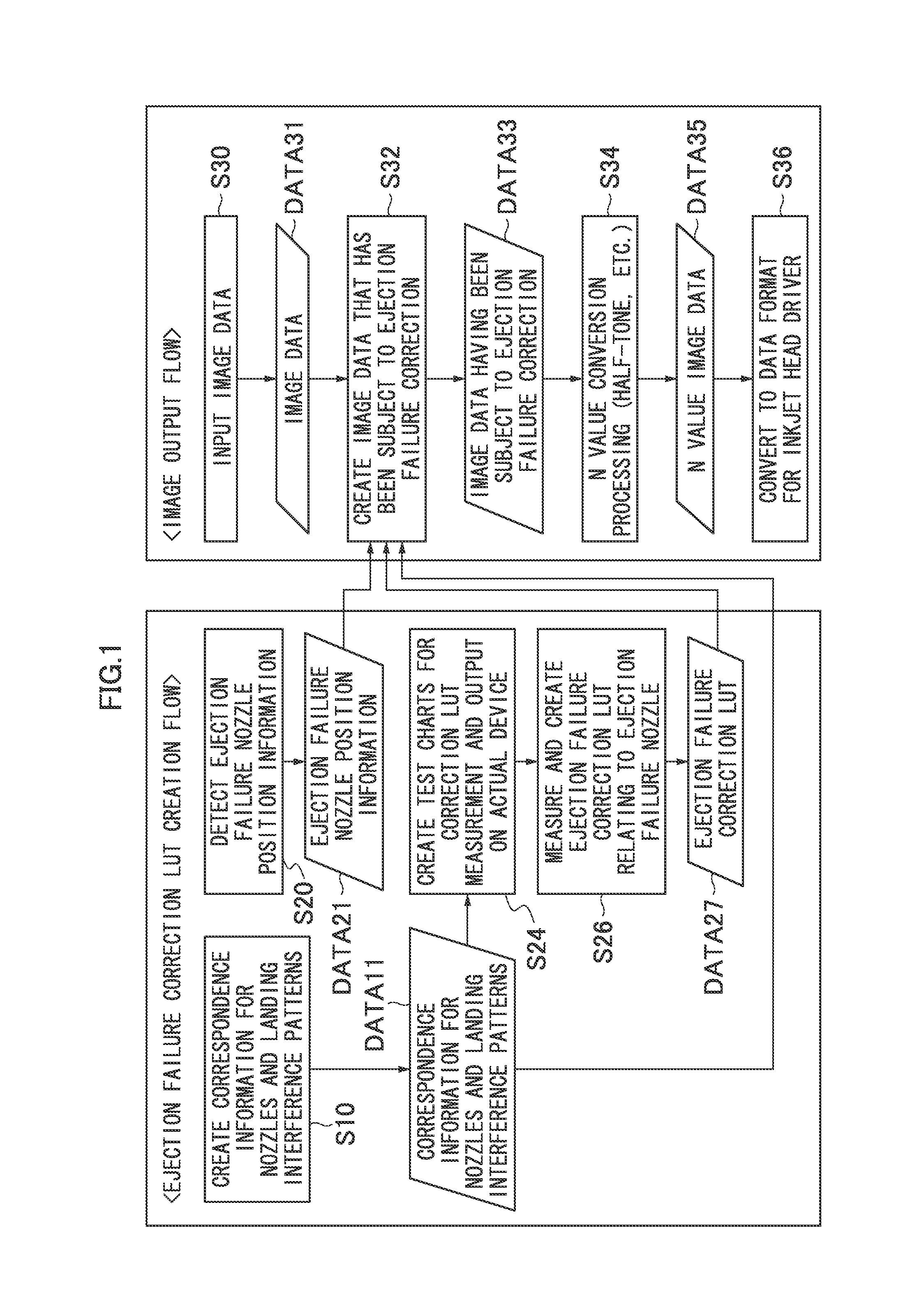
[0070]FIG. 1 is a flowchart of an image processing method relating to one embodiment of the present invention. To give a general description of the overall flow of image correction processing according to the present embodiment, firstly, [1] a test chart for ejection failure correction LUT measurement is output, [2] an ejection failure correction LUT is created by analyzing this test chart, and [3] correction of the image data is carried out using the ejection failure correction LUT thus created. In FIG. 1, steps until obtaining the ejection failure correction LUT (DATA 27 in FIG. 1) are called the “ejection failure correction LUT creation flow”, and steps of actually performing a correction process of the input image data by using this ejection failure correction LUT (S30 to S36 in FIG. 1) are called the “image output flow”.

Description of Ejection Failure Correction LUT Creation Flow

[0071]Firstly, the ejection failure correction LUT creation flow will be described. In the present e...

second embodiment

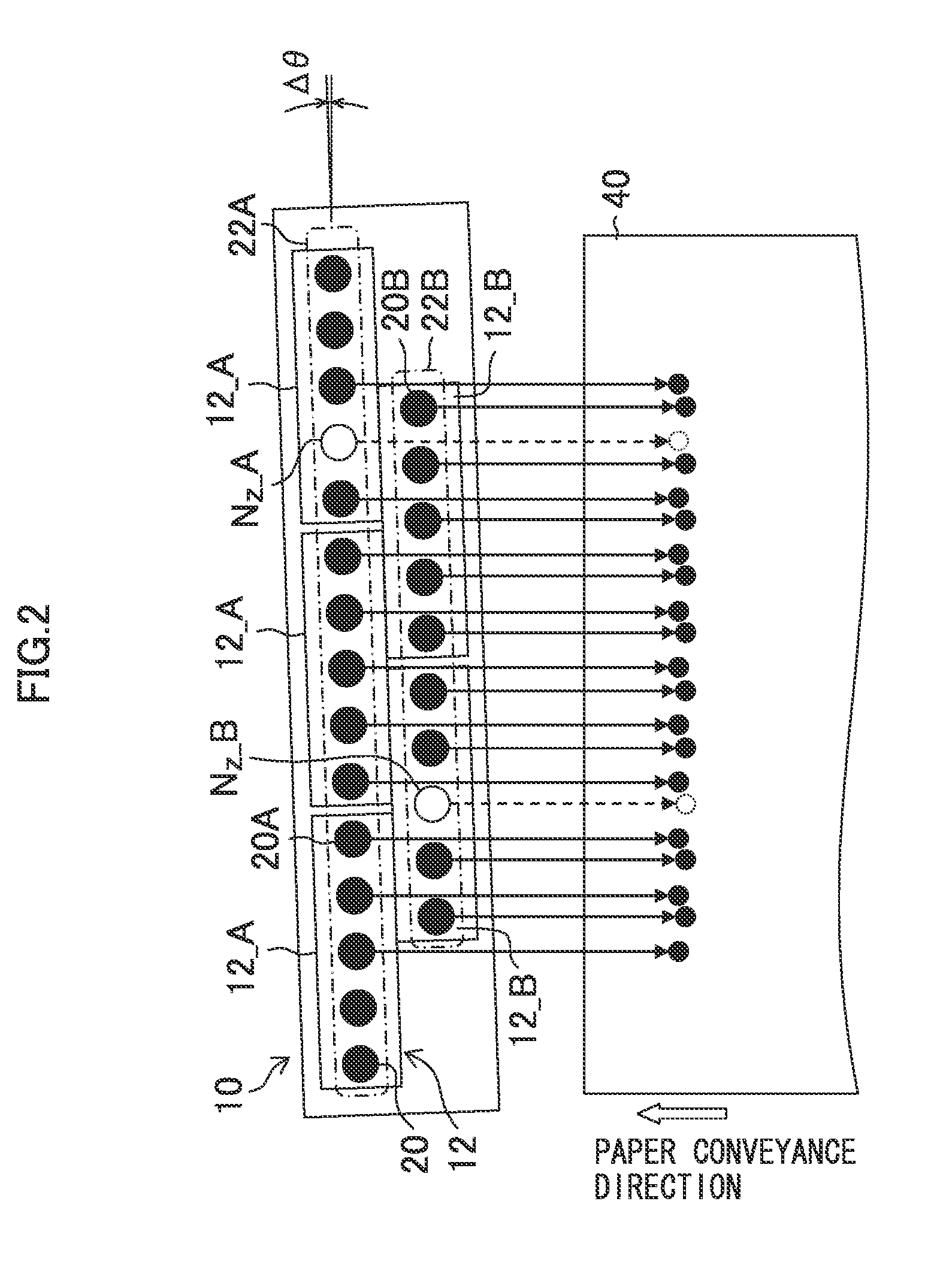
[0112]In the first embodiment, an example is given in which the nozzles in a head module 12 are arranged in a line shape. In implementing the present invention, the mode of arrangement of the nozzles is not limited to this. The second embodiment describes an example where nozzles are arranged in a matrix fashion. FIG. 6 shows an example of a nozzle arrangement of a head module 50 relating to the second embodiment. If the conveyance direction of the paper 40 is taken to be the y direction and the paper width direction perpendicular to this is taken to be the x direction, the nozzle arrangement of the head module 50 has four nozzle rows which have different positions in the y direction. The lowest level in FIG. 6 is called a first nozzle row, the level above this is called the second nozzle row, the level above this is called the third nozzle row, and the uppermost level is called a fourth nozzle row.

[0113]Looking in particular at each of the nozzle rows, the nozzle pitch Pm in the x ...

modification example 1

[0125]In the first embodiment and the second embodiment, ejection failure correction is carried out by raising the image setting values before and after an ejection failure nozzle. Instead of, or in combination with, the correction of image setting values of this kind, it is also possible to perform ejection failure correction by increasing the dot diameter or raising the droplet ejection density before and after an ejection failure nozzle. Furthermore, in FIG. 1, correction is applied to the image data before the N value conversion processing, but it is also possible to adopt a mode in which correction is applied to image data after the N value conversion processing (image data converted to N values).


PUM


Abstract

An image processing method of creating image data for forming an image on a recording medium by ejecting liquid droplets from a plurality of nozzles of a recording head onto the recording medium while causing relative movement of the recording medium and the recording head, includes: a correction coefficient storage step of determining correction coefficients for ejection failure correction based on difference of landing interference patterns of a plurality of types, according to correspondence information indicating correspondence relationship between the landing interference patterns and the respective nozzles, the landing interference patterns being based on a landing interference inducing factor including a deposition sequence of the liquid droplets on the recording medium that is defined by an arrangement configuration of the plurality of nozzles and a direction of the relative movement, and storing the correction coefficients for ejection failure correction according to the landing interference patterns, in a storage unit; an ejection failure nozzle position information acquisition step of acquiring ejection failure nozzle position information indicating a position of an ejection failure nozzle which cannot be used for forming the image, of the plurality of nozzles; and a correction processing step of performing a correction calculation on input image data using a corresponding correction coefficient obtained by referring to the correction coefficients for ejection failure correction according to the ejection failure nozzle position information, so as to generate image data corrected in such a manner that output of the ejection failure nozzle is compensated by a nozzle other than the ejection failure nozzle.

Description

BACKGROUND OF THE INVENTION[0001]1. Field of the Invention[0002]The present invention relates to image correction technology for improving image quality declined due to nozzles suffering ejection failure in an inkjet image forming apparatus.[0003]2. Description of the Related Art[0004]In the field of inkjet image formation, various measures are adopted in order to achieve image formation of high resolution by means of an inkjet head; for example, as shown in FIG. 13, a head 300 is constituted by a structure in which a plurality of nozzle head modules 301 are arranged in a staggered configuration, and the recording position pitch Ax on the paper 340 (image receiving medium) is made narrower than the pitch Pm of the nozzles 320 in the head module 301, thereby raising the recording resolution, and so on. In the example in FIG. 13, a head 300 is composed so as to have a nozzle arrangement (staggered arrangement) whereby the recording position pitch Δx on the paper 340 is approximately P...

Claims


Application Information

Patent Timeline
IPC IPC(8): B41J29/38
CPCB41J2/2139
Inventor UESHIMA, MASASHI
Owner FUJIFILM CORP
Why Eureka
Try Eureka