Image generation apparatus

a technology of image generation and image, applied in the field of image generation technology, can solve the problems of difficult recognition of objects existing in boundary areas or passing through areas, difficult to recognize objects existing in boundary areas, and extremely deteriorating visibility level of object images in overlap areas, so as to reduce the overlap area of composite images caused by lighting of lighting apparatus, increase the data volume of shot images, and reduce the effect of data volum

Active Publication Date: 2011-09-29
FUJITSU GENERAL LTD
View PDF9 Cites 50 Cited by
  • Summary
  • Abstract
  • Description
  • Claims
  • Application Information

AI Technical Summary

Benefits of technology

[0013]Since the image generation apparatus changes two data volumes of the two shot images used in the overlap area of the composite image based on the lighting mode of the lighting apparatus, problems in the overlap area of the composite image caused by lighting of the lighting apparatus can be reduced.
[0014]According to another aspect of the invention, the controller increases the data volume of the shot image taken by a first on-vehicle camera of the two on-vehicle cameras whose optical axis heads toward an area that is lighted by the lighting apparatus, and decreases the data volume of the shot image taken by a second on-vehicle camera of the two on-vehicle cameras, in a case where the lighting apparatus is on, as compared to a case where the lighting apparatus is off.
[0015]Since the image generation apparatus increases the data volume of the shot image having proper brightness taken by the first on-vehicle camera, and decreases the data volume of the shot image taken by the se...

Problems solved by technology

In an example, the area outside of the front fender on the opposite side of a driver's seat becomes a blind area for a driver, and the driver hardly recognizes clearances between own vehicle and obstacles in the area.
Thus, it is difficult to recognize the o...

Method used


Image

  • Image generation apparatus
  • Image generation apparatus
  • Image generation apparatus

Examples


first embodiment

1. First Embodiment

[0035]

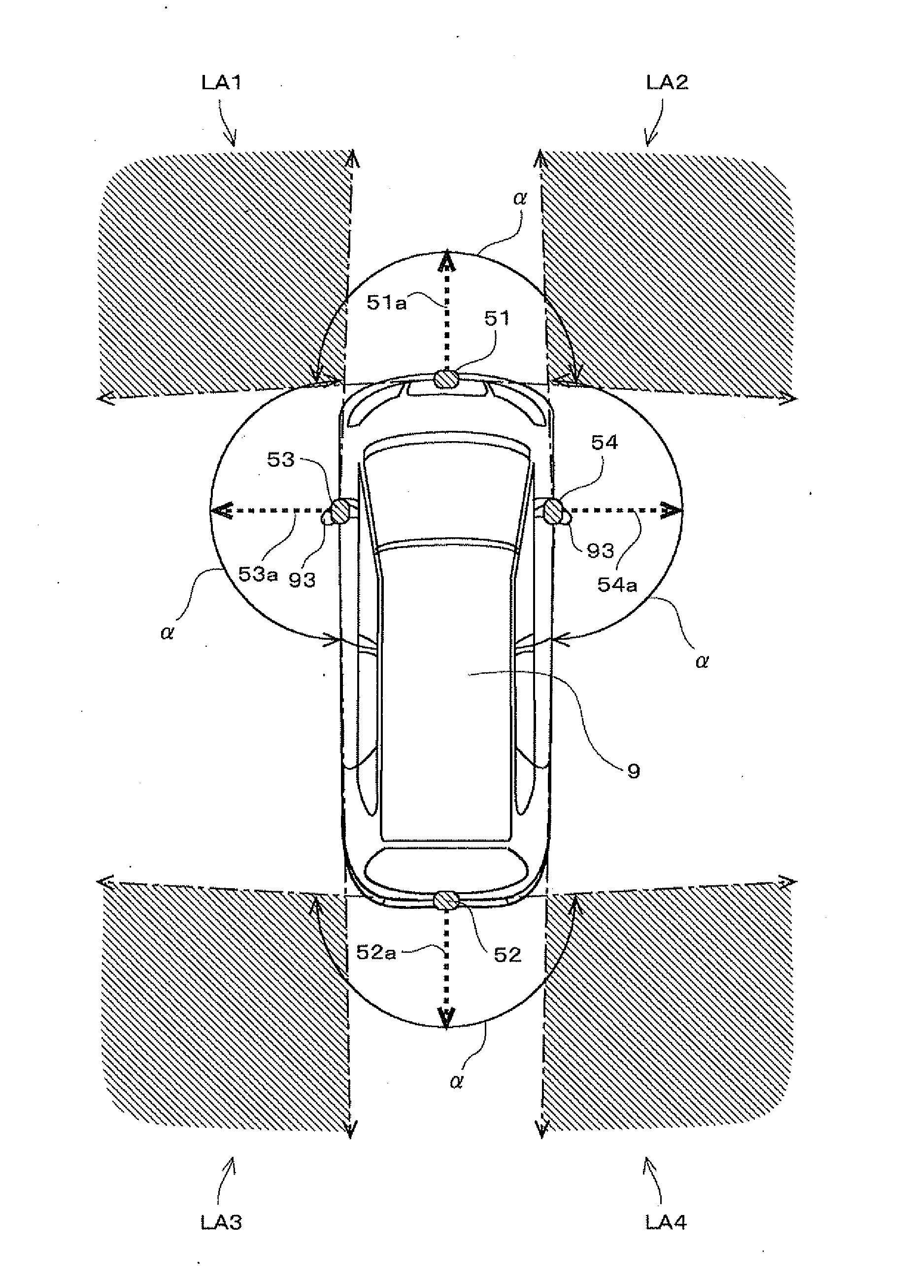
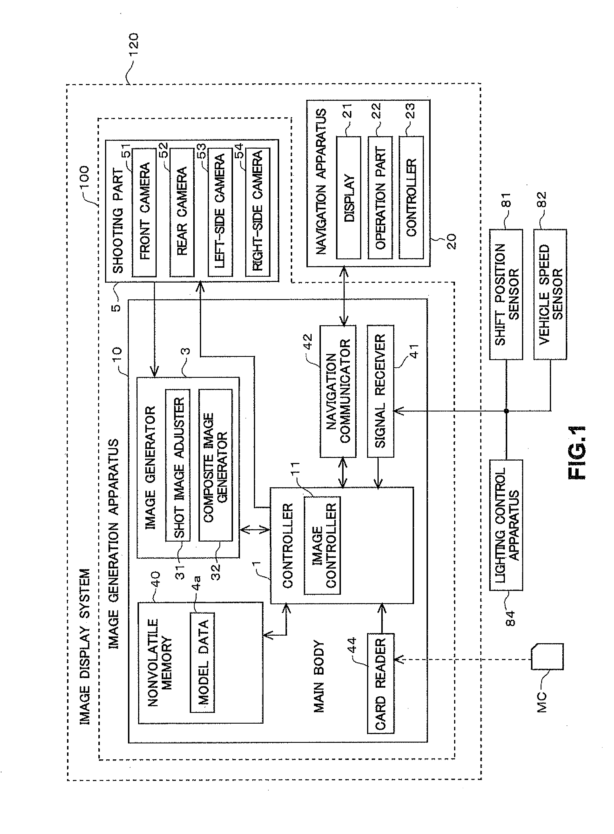
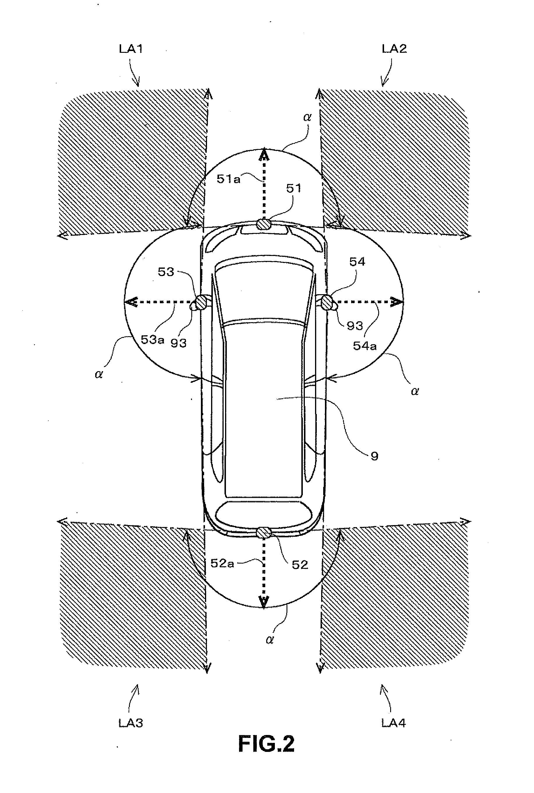
[0036]FIG. 1 is a block diagram showing a configuration of the first embodiment of an image display system 120. This image display system 120 is to be installed in a vehicle (a car in this embodiment) and has a function that shoots a surrounding area of a vehicle, and displays the generated images on a display disposed in a vehicle cabin. A user (typically a driver) of the image display system 120 can recognize the surrounding area of the vehicle in almost real time by using the image display system 120.

[0037]As shown in FIG. 1, the image display system 120 mainly includes an image generation apparatus 100 that generates images showing a surrounding area of a vehicle, and a navigation apparatus 20 that displays a variety of information to a user on a vehicle. The images generated by the image generation apparatus 100 are displayed on the navigation apparatus 20.

[0038]The navigation apparatus 20 that provides navigation assistance to a user includes a display...

second embodiment

2. Second Embodiment

[0123]This section describes the second embodiment. The second embodiment is almost the same as the first embodiment in its configuration and processing, but differs in some parts. Hereafter, the differences from the first embodiment are mainly described. In the case where lighting apparatuses are on, the second embodiment narrows the areas of the shot images where the alpha blending method is adopted as compared to the case where lighting apparatuses are not on.

[0124]FIG. 13 is a figure of the second embodiment, describing a method for deriving pixel values of the overlap areas OA1, OA2, OA3 and OA4 on the curved surface SP in the case where lighting apparatuses are on. In FIG. 13, the respective areas corresponding to the four shot images P1, P2, P3 and P4 are indicated by arrows with such respective shot image codes. FIG. 13 shows an example of the case that both of the headlights 98 and the brake lights 99 are on. However, in the case where only the headlight...

third embodiment

3. Third Embodiment

[0129]Next, this section describes the third embodiment. The third embodiment is almost the same as the first embodiment in its configuration and processing, but differs in some parts. Hereafter, the differences from the first embodiment are mainly described. In the case where lighting apparatuses are on, the third embodiment uses, in the overlap areas, only the shot images which are taken by an on-vehicle camera whose optical axis heads toward the area lighted by lighting apparatuses. (i.e. shot images in which object images are displayed in proper brightness.)

[0130]FIG. 14 is a figure of the third embodiment, describing a method for deriving pixel values of the overlap areas OA1, OA2, OA3 and OA4 on the curved surface SP in the case where lighting apparatuses are on. In FIG. 14, the respective areas corresponding to the shot images P1, P2, P3 and P4 are indicated by arrows with such respective shot image codes. FIG. 14 shows an example of the case that both of t...


PUM


Abstract

An image display system is capable of generating a composite image that shows a surrounding area of a vehicle viewed from virtual viewpoints, by combining a plurality of shot images taken by a plurality of on-vehicle cameras that are disposed at different locations on the vehicle. The image display system changes data volumes of two shot images taken by two of the on-vehicle cameras based on a lighting mode of a lighting apparatus, the data volumes being used for an overlap area of the composite image that corresponds to the surrounding area of the vehicle where the two on-vehicle cameras can shoot in overlap. This reduces problems caused by lighting of the lighting apparatus in the overlap area of the composite image.

Description

BACKGROUND OF THE INVENTION[0001]1. Field of the Invention[0002]The invention relates to an image generation technology of an image for display on a display apparatus that is installed in a vehicle.[0003]2. Description of the Background Art[0004]Conventionally, an image display system that is installed in a vehicle and that displays, on an in-vehicle display, images of surrounding area taken by on-vehicle cameras is known. A driver can view a surrounding area of a vehicle in almost real time by using this image display system.[0005]In an example, the area outside of the front fender on the opposite side of a driver's seat becomes a blind area for a driver, and the driver hardly recognizes clearances between own vehicle and obstacles in the area. On the other hand, using the image display system, images of the area outside of the front fender are taken by on-vehicle cameras and are displayed on a vehicle-cabin display. This system helps a driver to recognize easily clearances between...

Claims


Application Information

Patent Timeline
IPC IPC(8): H04N7/18
CPCB60R1/00B60R2300/103B60R2300/105B60R2300/304H04N7/181H04N5/23293H04N5/247H04N5/2624B60R2300/60H04N23/63H04N23/90
Inventor YAMADA, MASAHIROMATSUOKA, AZUSATANIGUCHI, SUSUMU
Owner FUJITSU GENERAL LTD
Why Eureka
Try Eureka