

Image processor, electronic camera, and image processing program
- Summary
- Abstract
- Description
- Claims
- Application Information
AI Technical Summary
Benefits of technology
Problems solved by technology
Method used
Image

Examples
first embodiment
The first embodiment has the advantages described below.
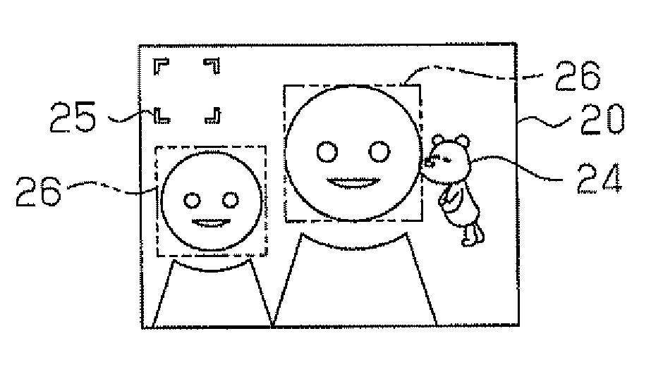
(1) The image processor displays a moving image in a pattern that changes in accordance with the image analysis information of a feature included in an image. The image processor changes the display pattern of the moving image in a variety of manners in accordance with image analysis information of a feature included in an image. This allows for a wide variety of special effects using a moving image to be added to images of different image contents.
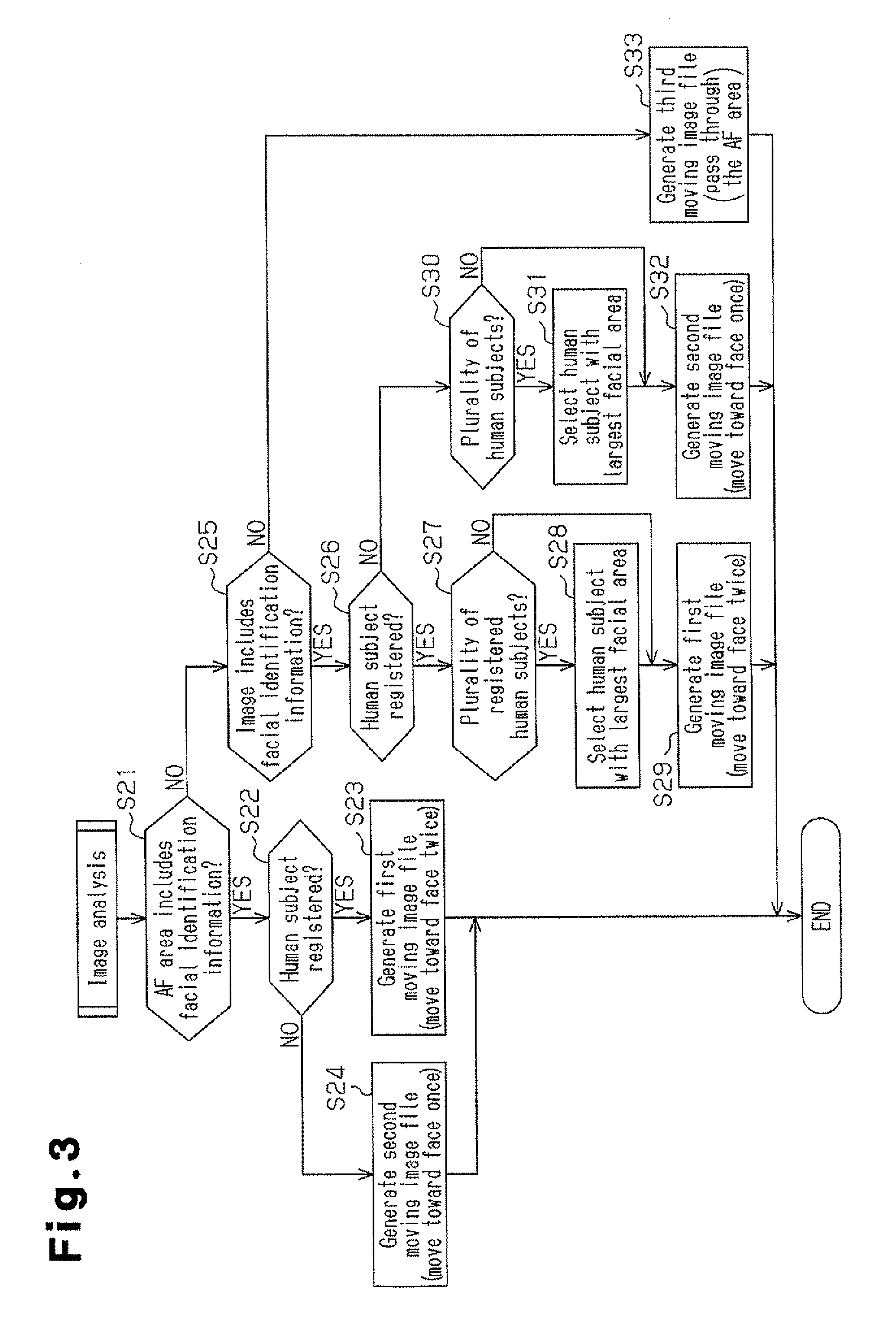
(2) Even when a plurality of features is included in a single image, the image processor selects the feature given priority in accordance with the image analysis information of the features. This adds a special effect using a moving image to emphasize at least one feature selected from the plurality of features.
(3) In accordance with the type of the cartoon character 24 generated and displayed as a moving image, the image processor selects, from a plurality of information elements ob...
second embodiment
the present invention has the advantage described below in addition to advantages (1) to (7) of the first embodiment.
(11) The image processor generates a moving image file in advance before a captured image is reproduced and displayed. This prevents a large processing load from being applied to the MPU 16 even when the MPU 16 superimposes a complicated moving image on a captured image.
Third Embodiment
A third embodiment of the present invention will now be discussed. The third embodiment differs from the first embodiment only in that a first image analysis routine and a second image analysis routine are performed when a moving image file is generated. The difference from the first embodiment will be described below. Parts that are the same as the first embodiment will not be described.
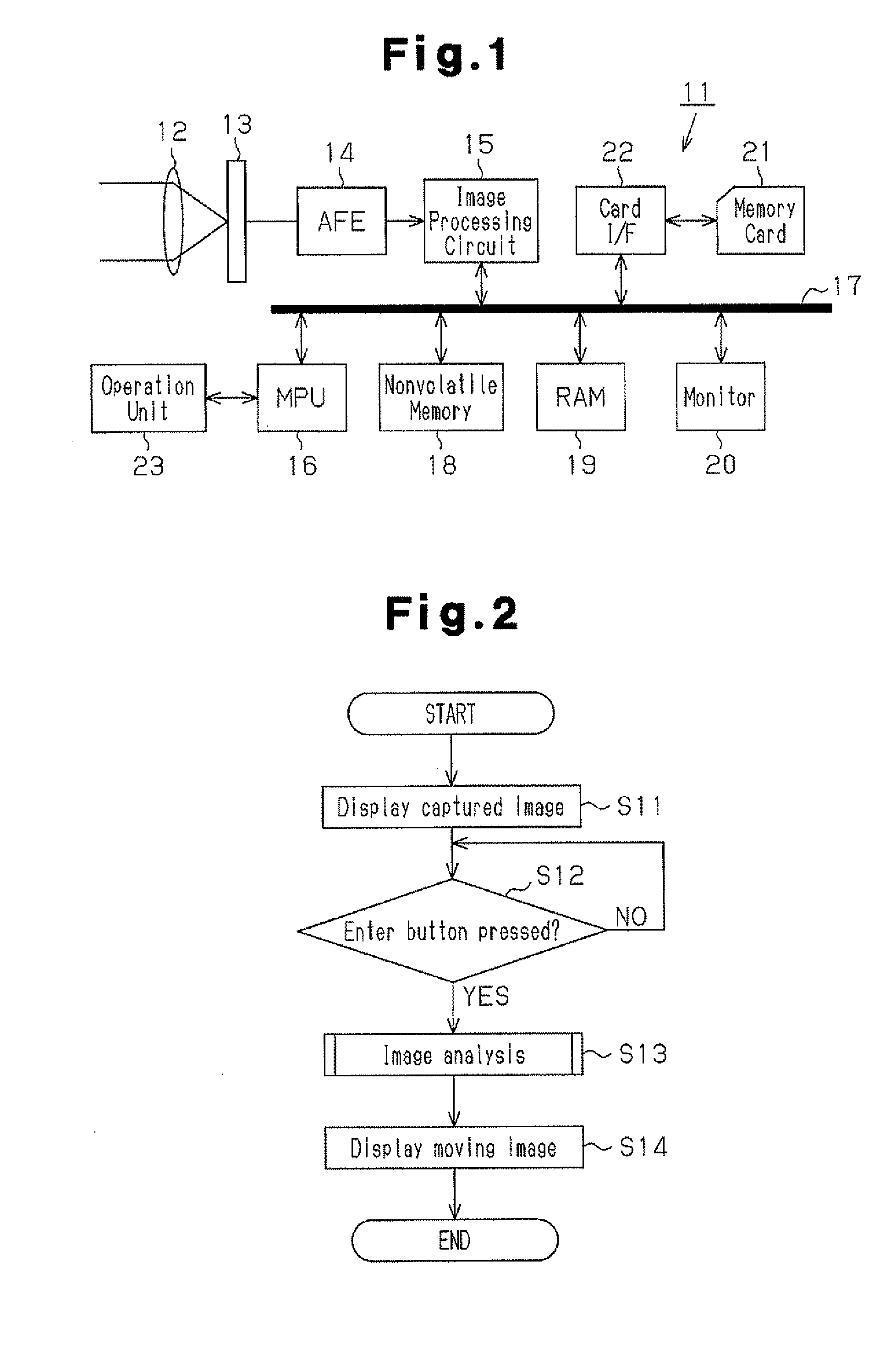
As shown in FIG. 11, the MPU 16 performs the processes of steps S61 and S62 that are similar to the processes of steps S11 and S12 shown in FIG. 2. Then, in step S63-1, the MPU 16 performs a first image...
third embodiment
The third embodiment has the advantages described below in addition to advantages (1) to (10) of the first embodiment.
(12) The moving image is displayed in a wide variety of appearances in accordance with the image analysis information (for example, the white cartoon character 73 is displayed). This allows for a special effect process that adds a variety of superimposed moving images in accordance with the contents of each image.
(13) The image processor changes the form of the cartoon character 73 displayed as a moving image in accordance with the color occupation ratio, which is an analysis information element of an image. Thus, a wide variety of special effects using superimposed moving images may be added to images of different color arrangements in accordance with the color arrangement of each image.
(14) The image processor displays, as a moving image, a cartoon character 73 having a color that is complementary to the color having the highest occupation ratio in the entire image...
PUM
 Abstract
Description
Claims
Application Information