

Image forming optical system and electronic image pickup apparatus using the same
a technology of optical system and electronic image pickup, which is applied in the field of image forming optical system, can solve the problems of insufficient size and insufficient image forming performance, and achieve the effect of improving image forming performance and forming performan
- Summary
- Abstract
- Description
- Claims
- Application Information
AI Technical Summary
Benefits of technology
Problems solved by technology
Method used
Image

Examples
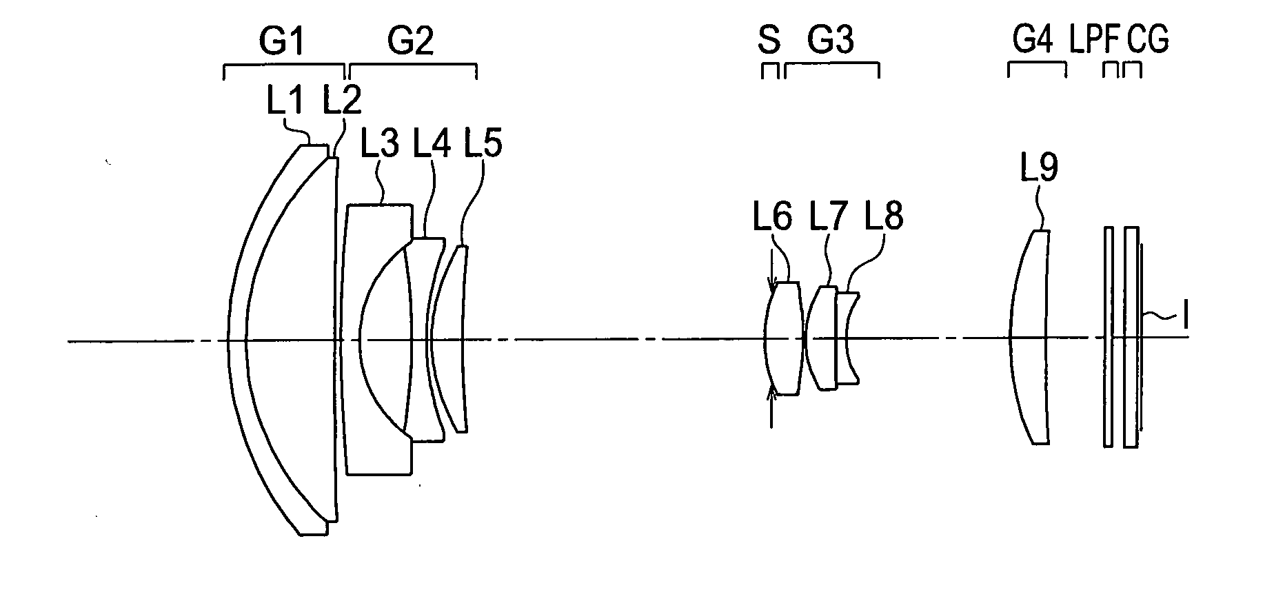
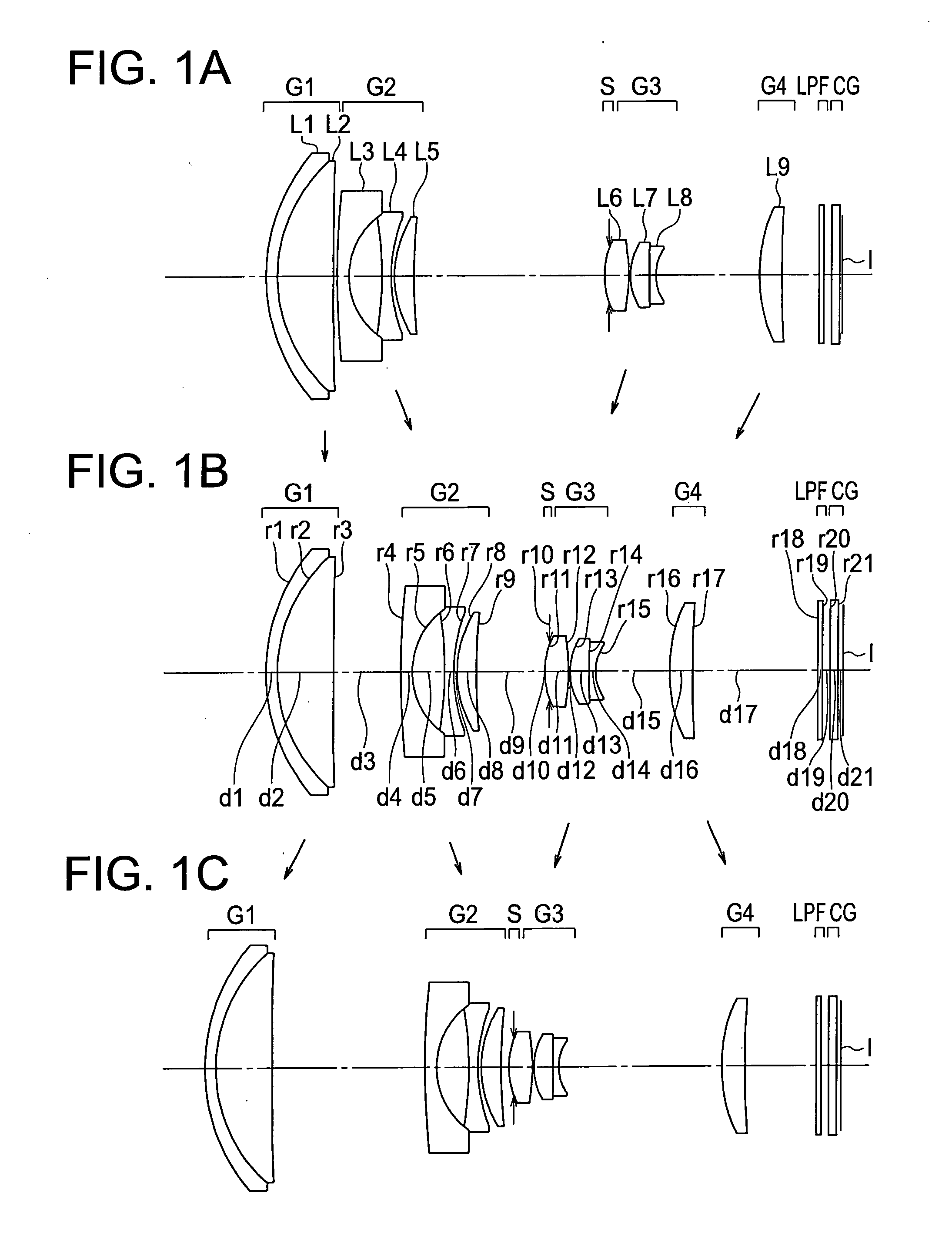
example 1
[0168]
Unit mmSurface dataSurface no.rdndνdERObject plane∞∞ 112.20510.70001.9459517.987.522 29.92983.51621.6226358.167.020 3*20365.6694Variable6.800 454.09940.75001.8830040.765.122 54.80622.10003.655 6−22.69620.60001.6935053.213.800 7*9.59740.20003.429 8*6.47511.26541.6298019.203.447 939.0927Variable3.40010(S)∞−0.30001.90011*4.99061.50001.5163364.141.94812*−11.71570.10001.875133.96021.20351.6935053.211.77314126.71990.40001.9036631.311.545152.9820Variable1.56316*10.82651.45001.5311055.914.0021772.3763Variable4.00018∞0.30001.5163364.144.11019∞0.50004.11520∞0.67901.5163364.144.127Image plane∞(Light receivingsurface)Aspherical surface data3rd surfaceκ = 0.000A4 = 4.02872e−05, A6 = −1.74846e−07, A8 = 2.73292e−09,A10 = −2.09410e−117th surfaceκ = 0.124A4 = −3.96733e−04, A6 = 2.25803e−05, A8 = −7.63555e−078th surfaceκ = −0.937A4 = −1.98542e−04, A6 = 1.13819e−05, A8 = −3.41417e−0711th surfaceκ = 0.000A4 = −7.61090e−04, A6 = 9.17926e−0512th surfaceκ = −10.084A4 = −9.59804e−05, A6 = 1.36092e−04...
example 2
[0169]
Unit mmSurface dataSurface no.rdndνdERObject plane∞∞ 114.03820.68991.9459517.987.673 210.60230.36651.6338723.387.074 311.56972.86241.6779055.347.048 4*−75793.8403Variable6.800 593.91630.63631.8830040.765.233 65.15522.17343.862 7−41.10360.62741.7432049.343.800 8*8.95490.40483.631 9*6.71081.19331.6298019.203.6621054.8892Variable3.60011(S)∞−0.35002.11012*5.59101.16951.5163364.142.12213*−13.76710.10002.121144.45651.47881.6779050.722.0661515.36880.39442.0033028.271.807163.3863Variable1.65017*12.28792.00781.4970081.544.22118*−595.0683Variable4.23719∞0.30001.5163364.144.15020∞0.50004.14621∞0.50001.5163364.144.13722∞0.50104.132Image plane∞(Light receivingsurface)Aspherical surface data4th surfaceκ = 0.000A4 = 2.05540e−05, A6 = 1.98219e−09, A8 = −1.16761e−09,A10 = 1.19838e−118th surfaceκ = 1.028A4 = −1.31693e−03, A6 = 3.93380e−05, A8 = −1.05662e−069th surfaceκ = −1.206A4 = −7.82471e−04, A6 = 4.29259e−05, A8 = −7.87816e−0712th surfaceκ = 0.000A4 = −7.35163e−04, A6 = 2.89169e−0513th surf...
example 3
[0170]
Unit mmSurface dataSurface no.rdndνdERObject plane∞∞ 114.27820.65021.9459517.987.587 211.24233.02291.6779055.347.074 3*−73816.9294Variable6.800 482.63760.63931.8830040.765.220 55.11802.18723.853 6−38.93980.56431.7432049.343.800 7*9.37160.36333.644 8*6.65231.23481.6298019.203.672 948.8218Variable3.60010 (S)∞−0.35002.10011*5.67701.50001.5163364.142.10912*−13.63260.10002.110134.38431.41551.6779050.722.0551413.88240.39612.0033028.271.808153.3901Variable1.65016*13.87431.60001.4970081.544.07817*−908.1765Variable4.18618∞0.30001.5163364.144.12019∞0.50004.11720∞0.50001.5163364.144.11121∞0.50404.107Image plane∞(Lightreceivingsurface)Aspherical surface data3rd surfaceκ = 0.000A4 = 2.14759e−05, A6 = 2.21108e−08, A8 = −1.31981e−09,A10 = 1.18716e−117th surfaceκ = 1.861A4 = −1.49755e−03, A6 = 3.72890e−05, A8 = −9.74767e−078th surfaceκ = −1.680A4 = −6.84639e−04, A6 = 4.18018e−05, A8 = −5.50154e−0711th surfaceκ = 0.000A4 = −7.39357e−04, A6 = 2.58199e−0512th surfaceκ = 0.000A4 = 2.67649e−04, A6...
PUM
 Abstract
Description
Claims
Application Information