Projection type image display apparatus

Inactive Publication Date: 2011-09-29
MITSUBISHI ELECTRIC CORP
View PDF8 Cites 1 Cited by
  • Summary
  • Abstract
  • Description
  • Claims
  • Application Information

AI Technical Summary

Benefits of technology

[0010]According to the present invention, since the front side part of the folding mirror is held by the image display screen, a rigid reinforcement structure at an upper part of the image display apparatus is not required, so that it is possible to hold the folding

Problems solved by technology

Therefore, a width of the design frame has to be thickened, s

Method used


Image

  • Projection type image display apparatus
  • Projection type image display apparatus
  • Projection type image display apparatus

Examples


Example

First Illustrative Aspect

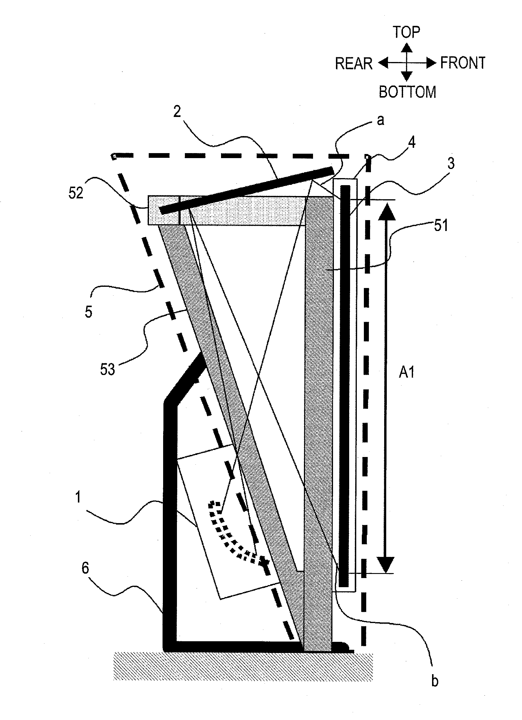
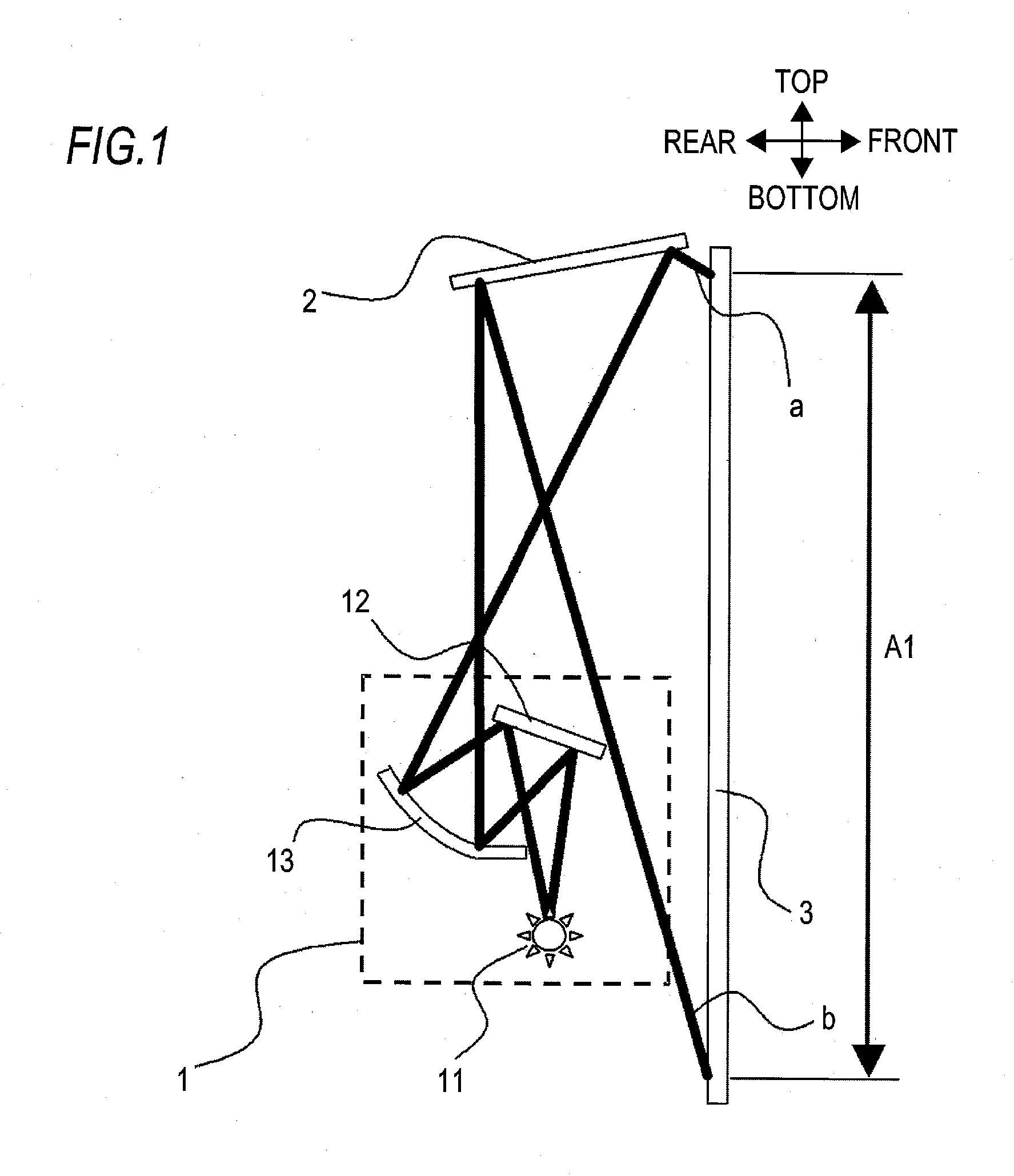
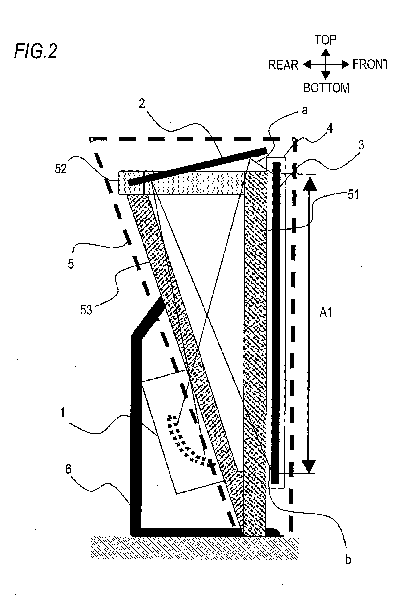
[0020]FIG. 1 is a side view showing an optical system of a projection type image display apparatus according to a first illustrative aspect of the invention. In this FIG. 1, an optical engine 1 includes a light source 11, a first folding mirror 12 and a non-planar mirror 13. A second folding mirror 2 reflects projected light from the optical engine 1 in an upward direction and the reflected light is projected on an image display screen 3, so that an image is displayed on the image display screen 3. The reflected light “a” indicates an upper end of the image projected on the screen 3 and the reflected light “b” indicates a lower end of the image. An image range A1 is a range from the reflected light “a” to the reflected light “b” and indicates a normal image range and a normal image position on the screen 3.

[0021]FIG. 2 is a side view showing a schematic structure of a frame of the projection type image display apparatus, FIG. 3 is a partial perspective secti...


PUM


Abstract

A projection type image display apparatus in one aspect of the present invention includes an optical engine that projects an image; an image display screen that displays an image of projection light projected from the optical engine; a folding mirror that reflects the projection light projected from the optical engine toward the image display screen; and an optical system support member that holds the optical engine, a rear side part of the folding mirror and the image display screen. The image display screen holds a front side part of the folding mirror by an upper side part of the image display screen.

Description

CROSS-REFERENCE TO RELATED APPLICATION[0001]This application claims priority from Japanese Patent Application No. 2010-066257 filed on Mar. 23, 2010, the entire subject matter of which is incorporated herein by reference.BACKGROUND[0002]1. Technical Field[0003]The present invention relates to a projection type image display apparatus, and specifically, to a thin projection type image display apparatus having a shallow depth.[0004]2. Background[0005]In a projection type image display apparatus, an optical engine makes light from a light source with information into image light. Then, the image light is reflected by a folding mirror and is projected on a screen, and an image is displayed on the screen. In order to prevent a distortion or a blur of the image, it is necessary to keep relative angle deviations between the optical engine, the screen and the folding mirror with high precision. Specifically, in order to suppress a deformation of the folding mirror, the mirror is thickened o...

Claims


Application Information

Patent Timeline
IPC IPC(8): G03B21/10G03B21/28G03B21/14G03B21/62
CPCG03B21/10G03B21/62G03B21/28
Inventor SUGANO, NORICHIKA
Owner MITSUBISHI ELECTRIC CORP
Why Eureka
Try Eureka