Resistance band exercise station

a resistance band and exercise station technology, applied in the field of resistance band exercise stations and wall-mounted exercise devices, can solve the problems of cumbersome closed loop anchoring devices, limitations that do not allow fitness and rehabilitation facilities to use standard resistance bands, and cannot accommodate all of the most commonly used resistance bands. , to achieve the effect of convenient and safe us

Active Publication Date: 2011-09-29
CORE ENERGY FITNESS SYST
View PDF49 Cites 58 Cited by
  • Summary
  • Abstract
  • Description
  • Claims
  • Application Information

AI Technical Summary

Benefits of technology

[0028]An object of the present invention is to provide a resistance band exercise station that is flexible, can accommodate various types of resistance bands and other exercise devices that require anchoring to a fixed object (e.g., suspension straps, stretch straps, ropes), and is easy and safe to use.

Problems solved by technology

(A) Most of the devices noted above do not accommodate all of the most commonly used types of resistance bands.
This limitation does not allow fitness and rehab facilities to use standard resistance bands, the number one piece of exercise equipment used by personal trainers and physical therapy professionals.
While effective, closed loop anchoring devices can be cumbersome and limit utilization of the most commonly used forms of resistance bands, i.e., standard resistance bands, JC Bands and flat bands.
Furthermore, closed loop anchoring devices do not facilitate transitions between resistance band exercises.
It is inconvenient and wastes time.
In many cases, users permanently affix a number of bands of different levels of resistance to one closed loop because it is too cumbersome to fasten and unfasten bands through these types of anchors.

Method used


Image

  • Resistance band exercise station
  • Resistance band exercise station
  • Resistance band exercise station

Examples


first embodiment

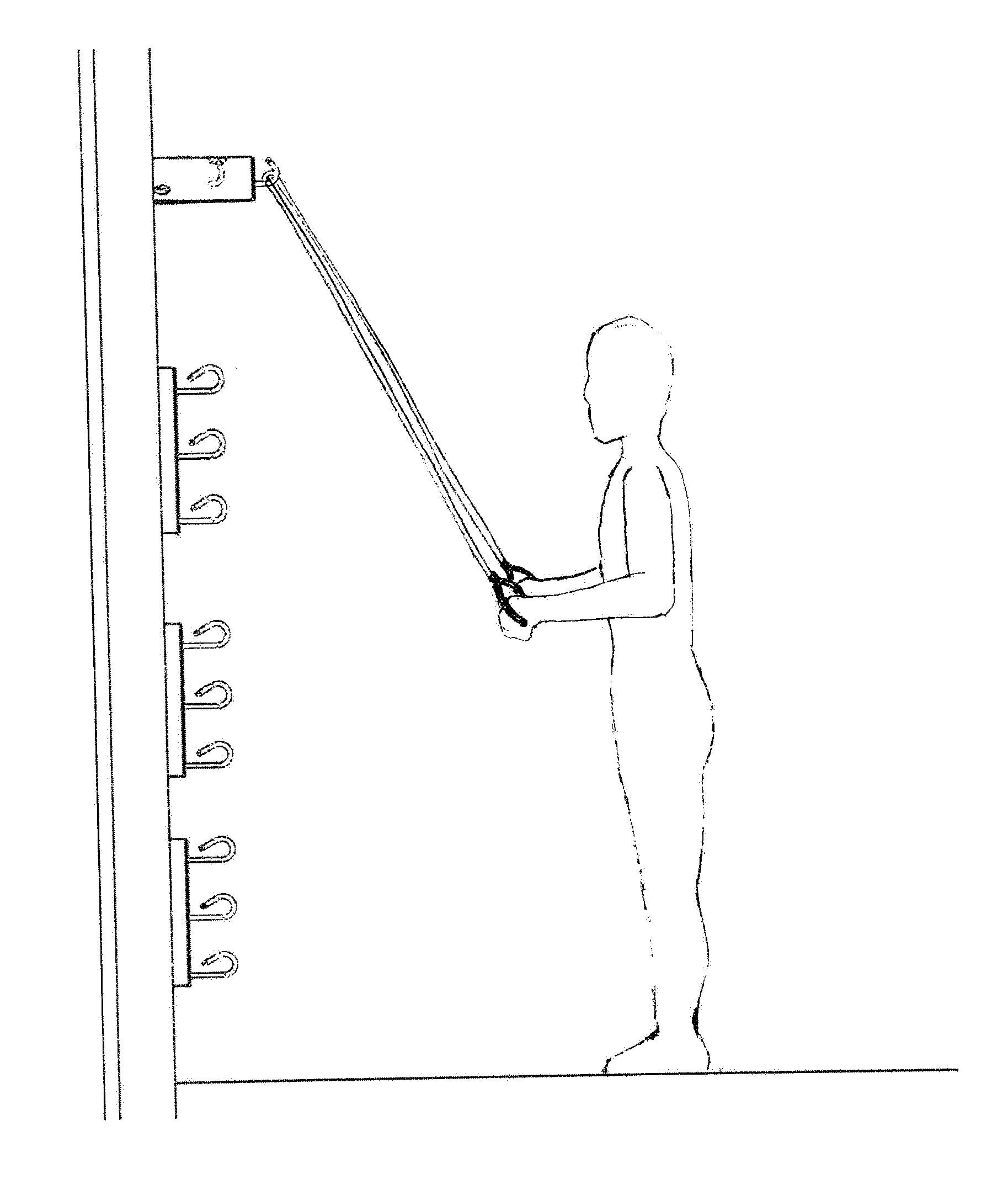
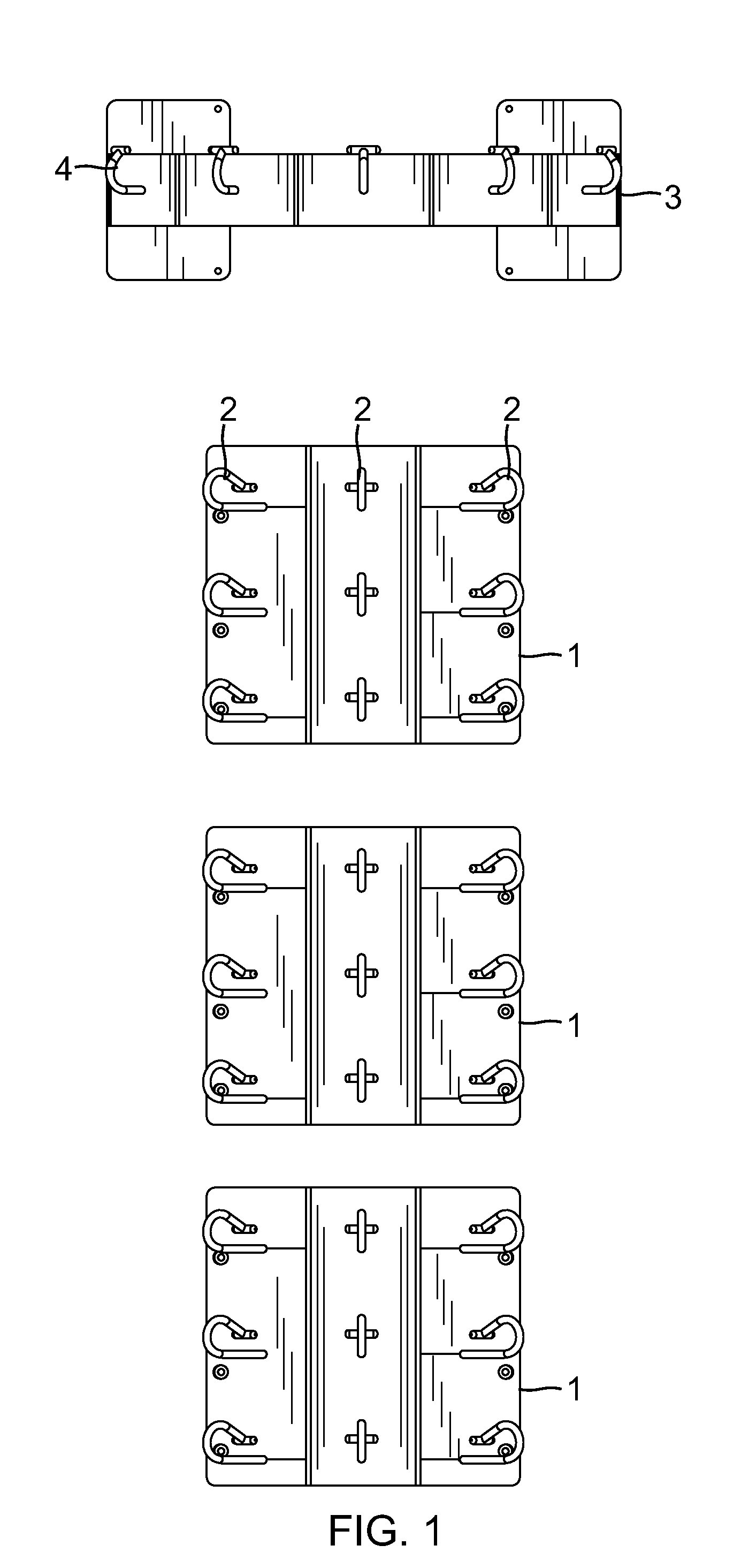
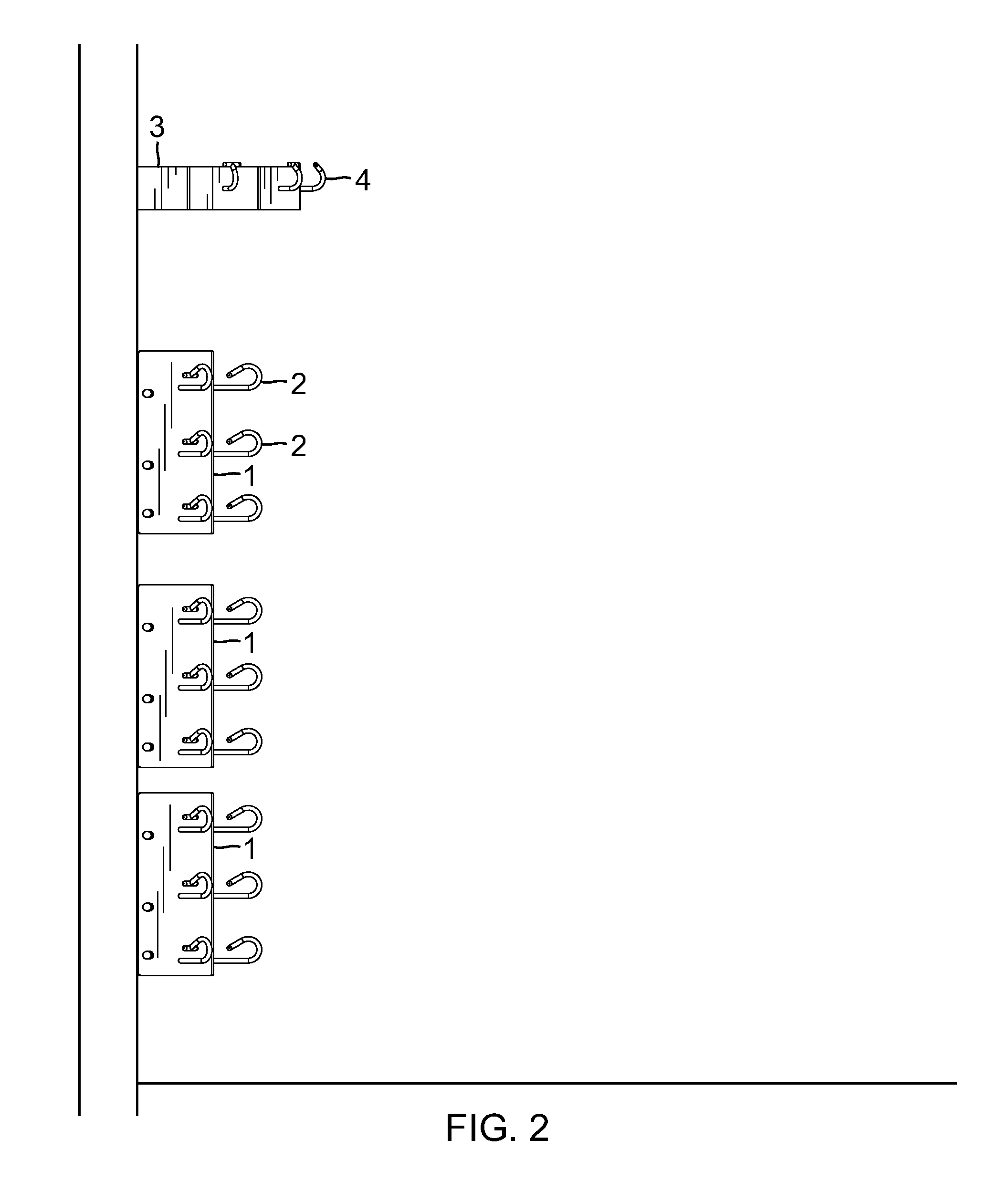
[0044]FIGS. 1-2 illustrate the general configuration of a resistance band exercise station according to the present invention (also referred to as the multi-station embodiment).

[0045]The resistance band exercise station of the first embodiment includes two components: one or more (three are shown in FIGS. 1-2) lower units 1 each including a vertically shaped mounting surface providing a strong and stable platform for column(s) of vertically spaced safety hooks 2 for exercises performed at various heights, from the ankle to eye level; and one or more (one is shown in FIGS. 1-2) upper units 3 each having a horizontally shaped mounting surface with a horizontal row of safety hooks 4 used for exercises performed above the head. Preferably, the resistance band exercise station has multiple lower and upper units 1 and 3 wall mounted in varying heights to provide anchoring points at key angles from ankle height to above the head. The safety hooks 2 and 4 are used to anchor resistance bands...

second embodiment

[0072]In use, when mounting the resistance band exercise station (either the first or second embodiment) in a fitness or rehabilitative environment, three lower units 1 are preferably mounted at approximately ankle height or six inches from the floor, waist height or about 36 inches from the floor and chest height or about 48 inches from the floor (measured from the center of each unit). One upper unit 3 is preferably mounted above the head or about seven feet from the floor. Other heights are also possible depending on need.

third embodiment

[0073]The exercise values of the resistance band exercise station of the embodiments shown and described above can also be accomplished by a simplified system. In a third embodiment shown in FIG. 17, a number of safety hooks 62 (two are shown here) are mounted directly to a flat mounting plate 61 to form a hoot plate 60. The safety hooks 62 may have the same or similar structures as the hooks 2 or 4 shown in FIGS. 13-16. The hook plate 60 can be directly mounted to the wall via a plurality of holes 63, and can be used even in homes. The mounting plate 61 can be a vertically oriented rectangular shaped plate or can be of another shape that provides sufficient structural support for the safety hooks. While the hooks 62, in the embodiment shown in FIG. 17, are arranged in a vertical column, they can also be configured in a horizontal row of hooks mounted to a horizontally oriented rectangular shaped mounting plate. In the embodiment shown in FIG. 17, two safety hooks 62 are mounted to ...


PUM


Abstract

The resistance band exercise station disclosed here is a modular hooking system used to perform a myriad of exercises with various exercise tools that require anchoring such as standard resistance bands, suspension straps and stretch straps. The resistance band exercise station includes multiple components: one or more lower units each having column(s) of vertically spaced safety hooks for exercises performed at various heights, from the ankle to eye level, and an upper unit having one or more safety hooks used for exercises performed above the head. The multiple lower and upper units are wall mounted in varying heights. The safety hooks are used to anchor resistance bands, suspension straps and stretch straps from one or multiple points. The safety hooks are open-loop hooks having a barrier member such as a T-bar at the tip to prevent the straps from slipping out.

Description

[0001]This application claims priority under 35 USC §119(e) from U.S. Provisional Patent Application No. 61 / 316,723, filed Mar. 23, 2010, which is herein incorporated by reference in its entirety.BACKGROUND OF THE INVENTION[0002]1. Field of the Invention[0003]The invention relates to exercise equipment and, in particular, it relates to wall mounted exercise devices that enable users to utilize standard resistance bands, suspension training straps and stretch straps in a number of exercise protocols and therapeutic applications.[0004]2. Description of the Related ArtResistance Bands[0005]Due to its low cost, portability, ease-of-use and versatility, resistance bands have become the leading exercise tool among personal trainers and physical therapists. With its simple, low cost design elements and broad fitness and therapeutic applications, resistance bands have achieved wide acceptance among fitness and therapeutic professionals and become a standard piece of exercise equipment that ...

Claims


Application Information

Patent Timeline
Patent Type & Authority Applications(United States)
IPC IPC(8): A63B21/04
CPCA63B21/0557A63B21/16A63B2021/169A63B21/0442A63B21/0552A63B2225/09A63B21/169
Inventor PEREZ, OSCAR
Owner CORE ENERGY FITNESS SYST
Why Eureka
Try Eureka