
HVAC Control System

a control system and hvac technology, applied in the field of energy saving programmable hvac systems, can solve the problems of large energy consumption of heating, ventilation and air conditioning systems, waste of energy, and time-consuming to heat or cool the environment to the desired temperatur

Active Publication Date: 2011-09-29
MITSUBISHI ELECTRIC RES LAB INC +1
View PDF4 Cites 29 Cited by
  • Summary
  • Abstract
  • Description
  • Claims
  • Application Information

AI Technical Summary

Benefits of technology

[0010]The HVAC is maintained in an ON state if the travel time is less than the conditioning time, and otherwise ma

Problems solved by technology

Heating, ventilation, and air conditioning (HVAC) systems consume a large amount of energy.
Because many environments may be unoccupied at times, this wastes energy.
However, the time required to heat or cool the environment to the desirable temperature takes considerable time, perhaps longer than the time that the environment is occupied.
However, this is impractical when the occupancy period is irregular, or the schedule changes frequently.
Schedules also do not accommodate holidays, vacations, travel, unplanned absence, and other changes to the occupancy routine.
Furthermore, the observed data from a limited time period typically would not include all possible combinations of indoor and outdoor temperatures that might be encountered in the future.
Another disadvantage of that system is the need to constantly re-compute and compare the travel time and conditioning time.
Since the GPS-enabled mobile device us typically powered by a battery, constant communication between the device and the conditioned space would quickly drain the mobile device's battery, and is also likely to result in costly data communications traffic.

Method used


Image

  • HVAC Control System
  • HVAC Control System
  • HVAC Control System

Examples


Embodiment Construction

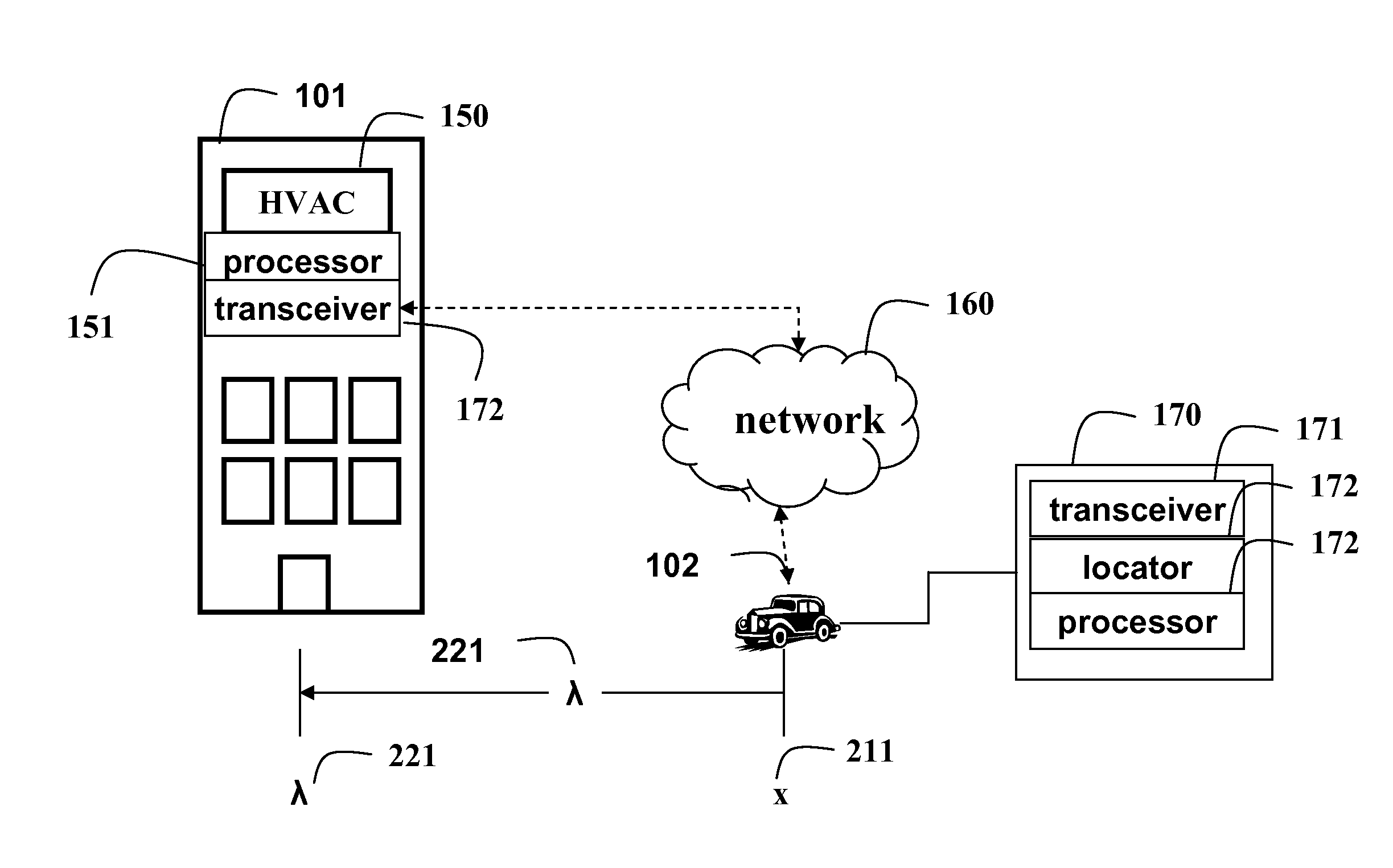
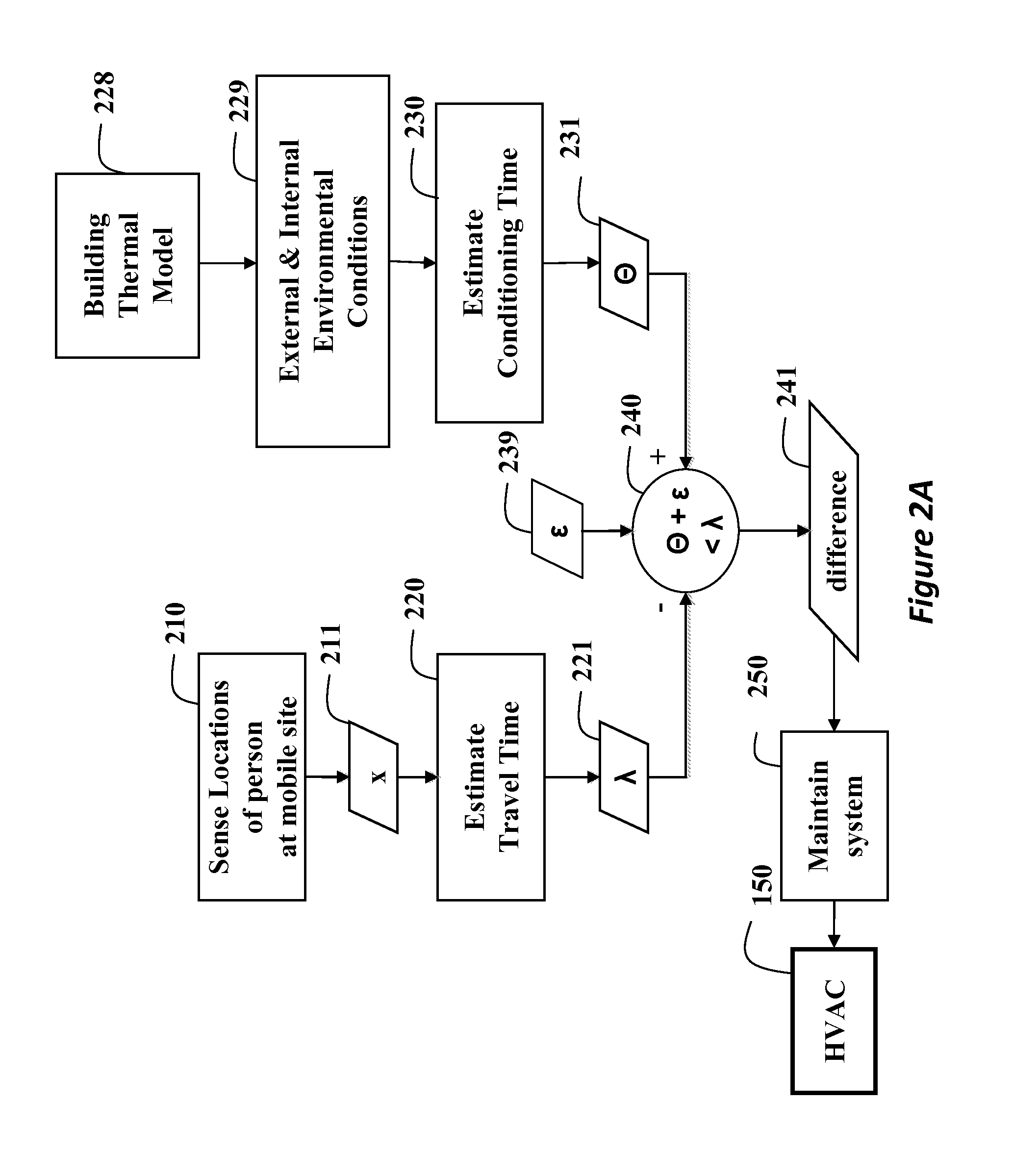
[0017]The embodiments of our invention provide a method for operating a heating, ventilation, and air conditioning (HVAC) system. The method uses a travel time for a person to reach the environment being controlled, and the conditioning time of the HVAC system.

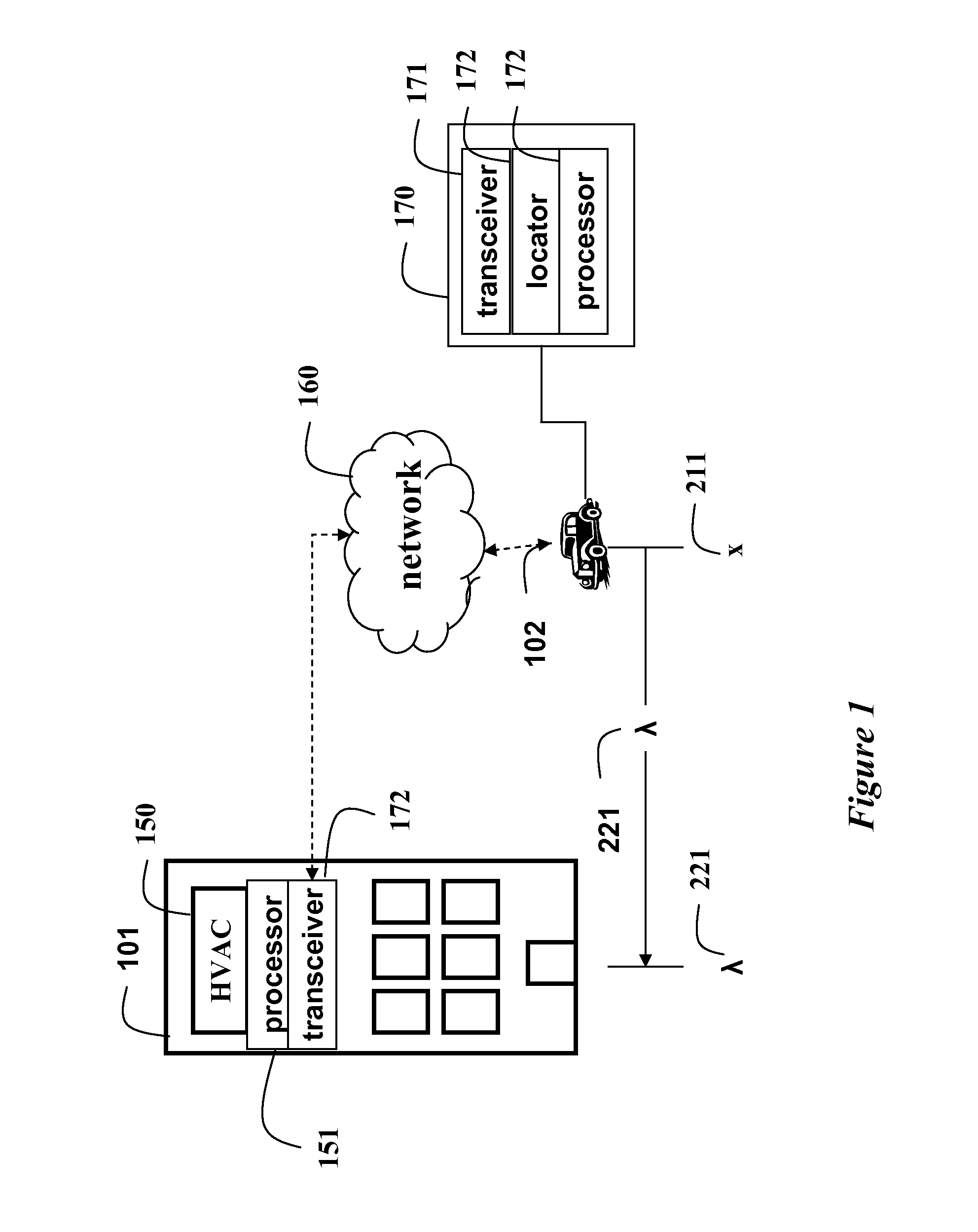
[0018]FIG. 1 shows a fixed site (a workplace) 101, and a mobile site 102 at a location x 211, e.g., the mobile site is traveling to the fixed site. The mobile site includes a person destined for the fixed site. The mobile site can be a car, public transportation, a bicycle, or a person carrying a mobile communications device 170. The device 170 includes a mobile transceiver 171, a mobile locator, and a mobile processor 172.

[0019]The fixed site 101 includes a HVAC system 150, which is connected to a fixed transceiver and a fixed processor 151 and a fixed transceiver 172 similar to the mobile transceiver 171. In a simplest form, the HVAC system includes a boiler, and perhaps air circulation means.

[0020]The fixed site and the mob...


PUM


Abstract

A method controls a heating, ventilation, air conditioning (HVAC) system by determining a travel time from a mobile site to a fixed site, and determining a conditioning time for a HVAC system at the fixed site. The HVAC is maintained in an ON state if the travel time is less than the conditioning time, and otherwise maintaining the HVAC in an OFF state, and wherein the conditioning time is determined using a building thermal model.

Description

FIELD OF THE INVENTION[0001]The invention relates generally to the field of heating, ventilation, and air conditioning (HVAC) systems, and more particularly to energy saving programmable HVAC systems.BACKGROUND OF THE INVENTION[0002]Heating, ventilation, and air conditioning (HVAC) systems consume a large amount of energy. Commonly, heating and cooling operations for an environment are controlled automatically with one or more thermostats. A thermostat can be located centrally, or thermostats can be distributed. Typically, the operation of the HVAC system is according to preset temperature limits.[0003]Because many environments may be unoccupied at times, this wastes energy. Occupancy can be determined with motion detectors. However, the time required to heat or cool the environment to the desirable temperature takes considerable time, perhaps longer than the time that the environment is occupied.[0004]An operation schedule can be used. However, this is impractical when the occupanc...

Claims


Application Information

Patent Timeline
IPC IPC(8): G05B15/00
CPCF24F11/006F24F2221/12F24F2011/0068F24F11/30F24F11/62F24F11/56F24F2120/12F24F11/58F24F11/46F24F11/63
Inventor NIKOVSKI, DANIELLAUGHMAN, CHRISTOPHER
Owner MITSUBISHI ELECTRIC RES LAB INC
Learn More