Upgraded type slipper

Inactive Publication Date: 2011-10-06
NOUVELLE
View PDF0 Cites 18 Cited by
  • Summary
  • Abstract
  • Description
  • Claims
  • Application Information

AI Technical Summary

Benefits of technology

[0016]In particular, the aim of the present invention is to make a slipper in which each anchorage element always maintain, in use and not in use, the correct position with respect to the sole, so that its base does not exit from the relative housing hole.
[0017]The present

Problems solved by technology

This type of slipper is not very practical because the user must, bef

Method used


Image

  • Upgraded type slipper
  • Upgraded type slipper
  • Upgraded type slipper

Examples


Example

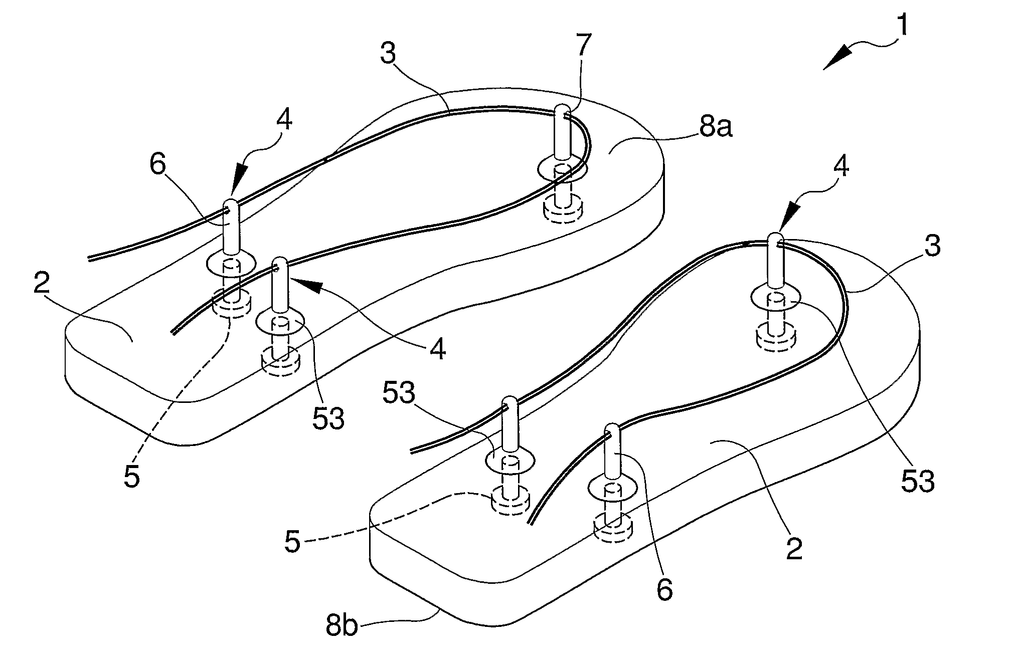
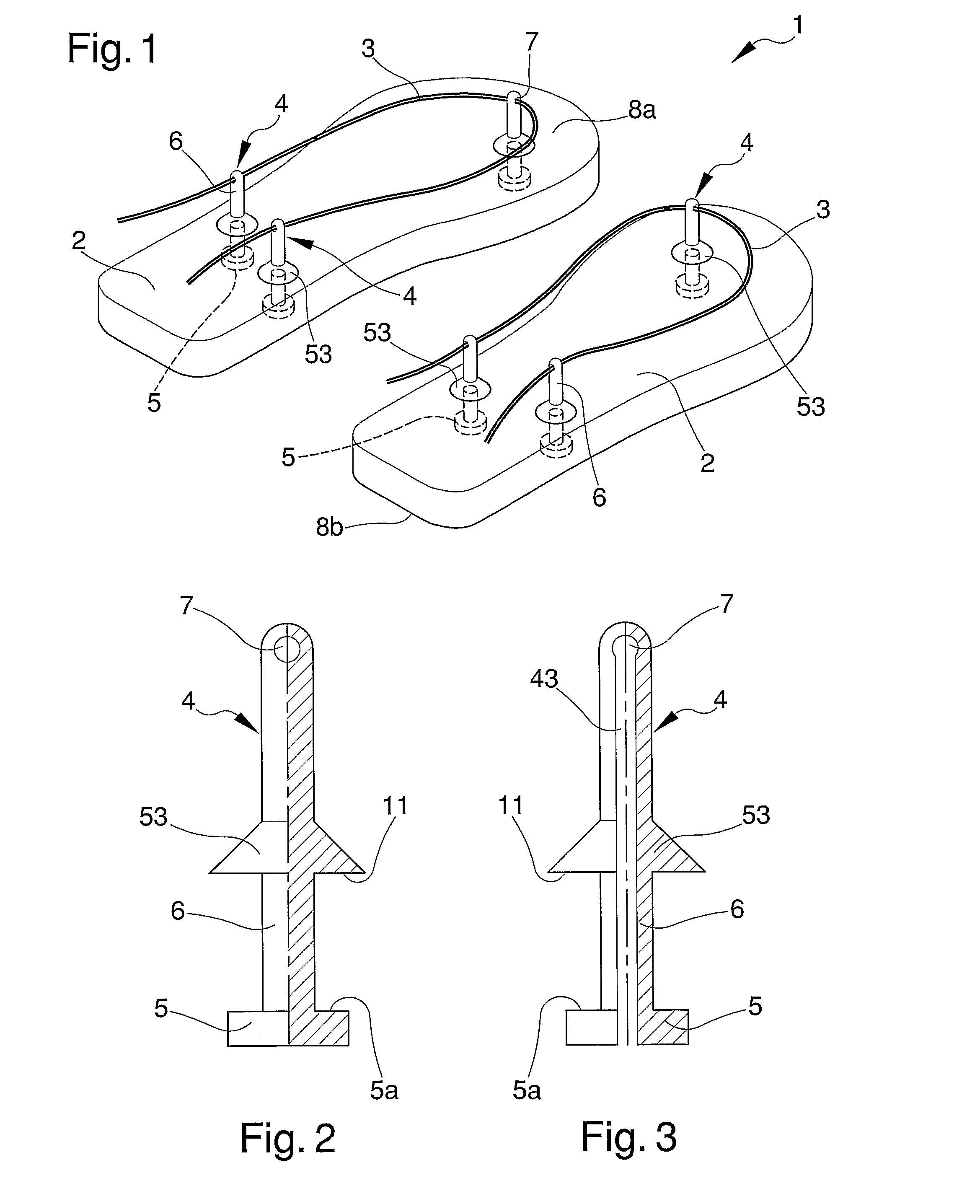
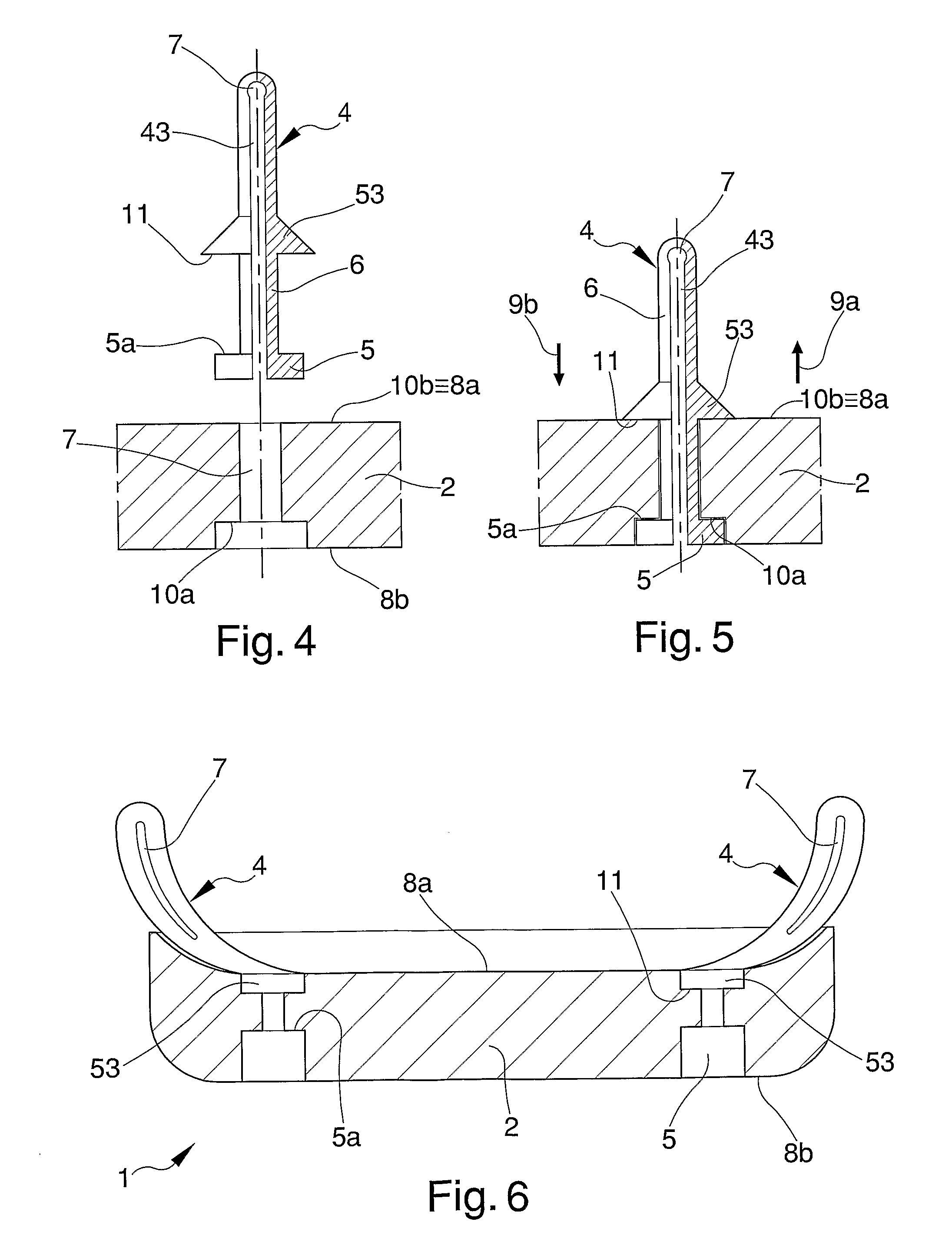
[0029]With reference to the mentioned illustrations, FIG. 1 shows a pair of slippers, each of which is generally indicated by the reference number 1, which comprises a sole 2 having a plurality of holes 2a, generally equal to three in number, and an upper anchored to the sole 2 by means of the holes 2a. The upper comprises at least a lace 3 and one or more anchorage elements 4 for retaining lace 3 to relative sole 2.

[0030]The sole 2 has an upper surface 8a, on which the foot rests, and a lower surface 8b in contact with the ground.

[0031]Advantageously, the sole 2 is made of an elastically yielding material. The anchorage elements 4, made separately from the lace 3, can be inserted in a removable way into sole 2 by intersection through holes 2a.

[0032]More in particular, the anchorage elements 4 according to the invention can have the same height, or different heights, from one another.

[0033]The anchorage elements according to the present invention can also have different shapes and ...


PUM


Abstract

The slipper comprises a sole having a plurality of holes, anchorage elements inserted into the holes, and a lace passed through holes in the anchorage elements to join the upper lace to the sole. Each anchorage element comprises a base, is housed in one of the holes in the sole, for cooperation with the sole to prevent the movement of the relative anchorage element along at least a first direction. A projection extends upwardly from the base of each anchorage element, and a through hole is defined in the projection to receive the lace. Each anchorage element may also include retention members for securing the position of the slipper with respect to the sole.

Description

CROSS-REFERENCE TO RELATED APPLICATIONS[0001]This application claims the benefit of PCT International Patent Application No. PCT / IB2009 / 007479, filed Nov. 17, 2009, and Italian Patent Application No. VI2008A000271, filed Nov. 18, 2008, in the Italian Patent and Trademark Office, the disclosures of which are incorporated herein by reference.BACKGROUND OF THE INVENTION[0002]1. Field of the Invention[0003]The present invention relates to an upgraded type slipper and particularly refers to flip-flop slippers.[0004]2. Description of the Related Art[0005]The upper of the flip-flop slipper of known type is made up of a shoelace, or lace, or strap, associated with a plurality of anchorage elements inserted, by deformation, in corresponding holes deformed on the sole of the slipper itself. The fastening by deformation occurs because the extremity of the anchorage elements, which has an essentially cylindrical appearance, is inserted in a relative housing seat passing through the correspondin...

Claims


Application Information

Patent Timeline
IPC IPC(8): A43B3/12
CPCA43B3/103
Inventor GIOVANNETTI, SIMONA
Owner NOUVELLE
Why Eureka
Try Eureka