Weight filling device for small objects

Active Publication Date: 2011-10-06
A & B PACKING EQUIP INC
View PDF4 Cites 12 Cited by
  • Summary
  • Abstract
  • Description
  • Claims
  • Application Information

AI Technical Summary

Benefits of technology

[0011]In another embodiment, the device further comprises a package conveyor assembly having a frame with a first conveyor and a second conveyor in a side by side orientation. Each of the first and second conveyors include a plurality of vertical stops extending therefrom, with a container to be filled being placed on the first and second conveyors simultaneously. Further independent adjustment of the first conveyor relative to the second conveyor is provided, to, in turn, adjust the position of the vertical stops of the first conveyor relative to the vertical stops of the second conveyor. Thus, the conveyor can facilitate the filling of differently sized containers.
[0012]In a preferred embodiment, the frame further includes a vertical adjustment assembly structurally configured to raise and lower the frame relative to the chute assembly. This, in turn, facilitates the filling of containers of varying height.
[0020]In yet another aspect of the invention, the invention comprises a weight filling device for filling small objects comprising: a vibrating feed assembly, at least one bin, a chute assembly and a package conveyor assembly. The vibrating feed assembly has at least one feed station. The feed station has at least one feed tray with a large feed portion and a small feed portion in a side by side orientation each extending to a distal end thereof. Further, a vibrating device imparts vibration to the feed tray at a predetermined frequency. The at least one bin is positioned so as to be placeable in communication with the distal end of the at least one feed tray. The chute assembly is positioned below the distal end of the at least one feed tray directing the small objects to the at least one bin. The package conveyor assembly has a frame with a first conveyor and a second conveyor in a side by side orientation. Each of the first and second conveyors include a plurality of vertical stops extending therefrom, with a container to be filled being placed on the first and second conveyors simultaneously. An independent adjustment of the first conveyor relative to the second conveyor is provided, to, in turn, adjust the position of the vertical stops of the first conveyor relative to the vertical stops of the second conveyor, thereby facilitating the filling of differently sized containers.

Problems solved by technology

Among other problems, it is often difficult to easily meter the product when getting close to the desired weight.
Often, the quick feed rate and the slow feed rate are related, and, as such it is difficult to optimize either.
Thus, the quick feed rate may suffer to insure that the slow feed rate is acceptable.
Conversely, the slow feed rate may suffer to insure that the quick feed rate is acceptable.
Additionally, it is often difficult to efficiently and quickly direct product between a plurality of product bins.
Often, it is difficult to inexpensively and accurately switch between bins, and the equipment utilized to do so is often cumbersome.
Still other difficulties comprise the ability to easily adapt the filling devices for differently sized and shaped containers.
Often, the height of the container forms a limitation as the container approaches the bottom of the bins.
Additionally, it is difficult to accommodate bins of different lengths as the conveyors are structurally configured to accept a narrow range of container lengths.

Method used


Image

  • Weight filling device for small objects
  • Weight filling device for small objects
  • Weight filling device for small objects

Examples


Embodiment Construction

[0034]While this invention is susceptible of embodiment in many different forms, there is shown in the drawings and described herein in detail a specific embodiment with the understanding that the present disclosure is to be considered as an exemplification and is not intended to be limited to the embodiment illustrated.

[0035]It will be understood that like or analogous elements and / or components, referred to herein, may be identified throughout the drawings by like reference characters. In addition, it will be understood that the drawings are merely schematic representations of the invention, and some of the components may have been distorted from actual scale for purposes of pictorial clarity.

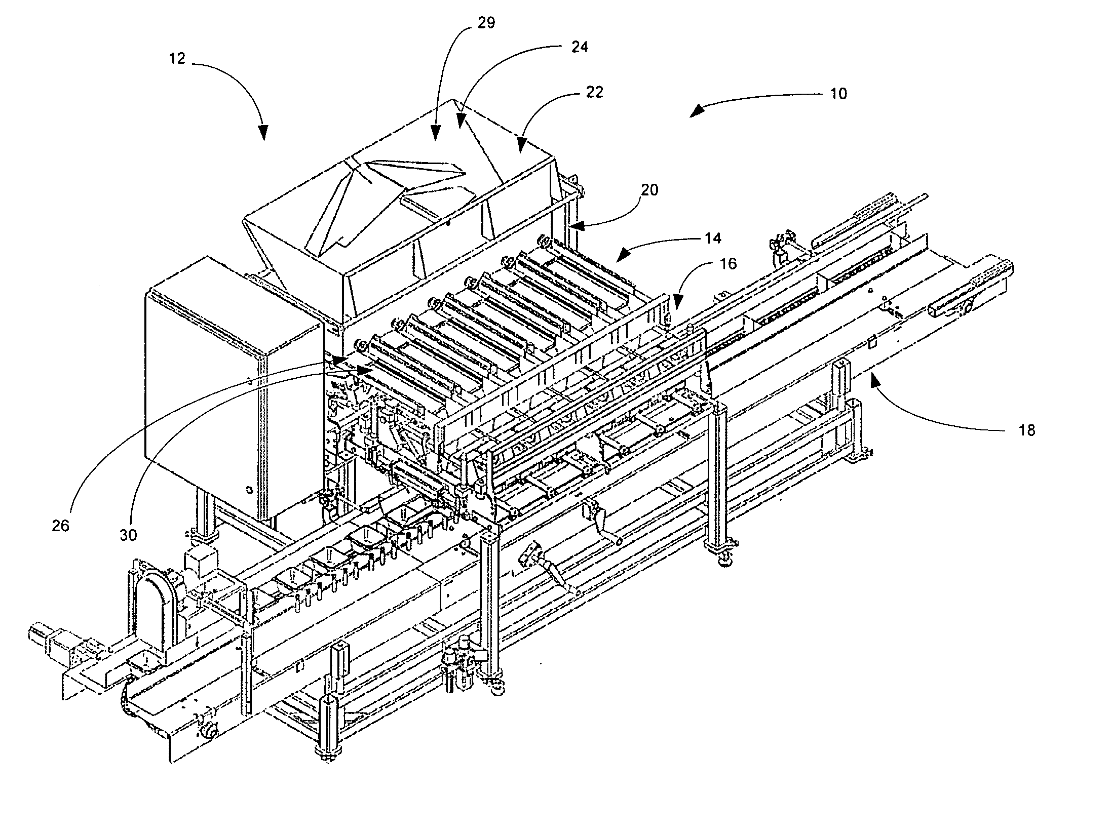
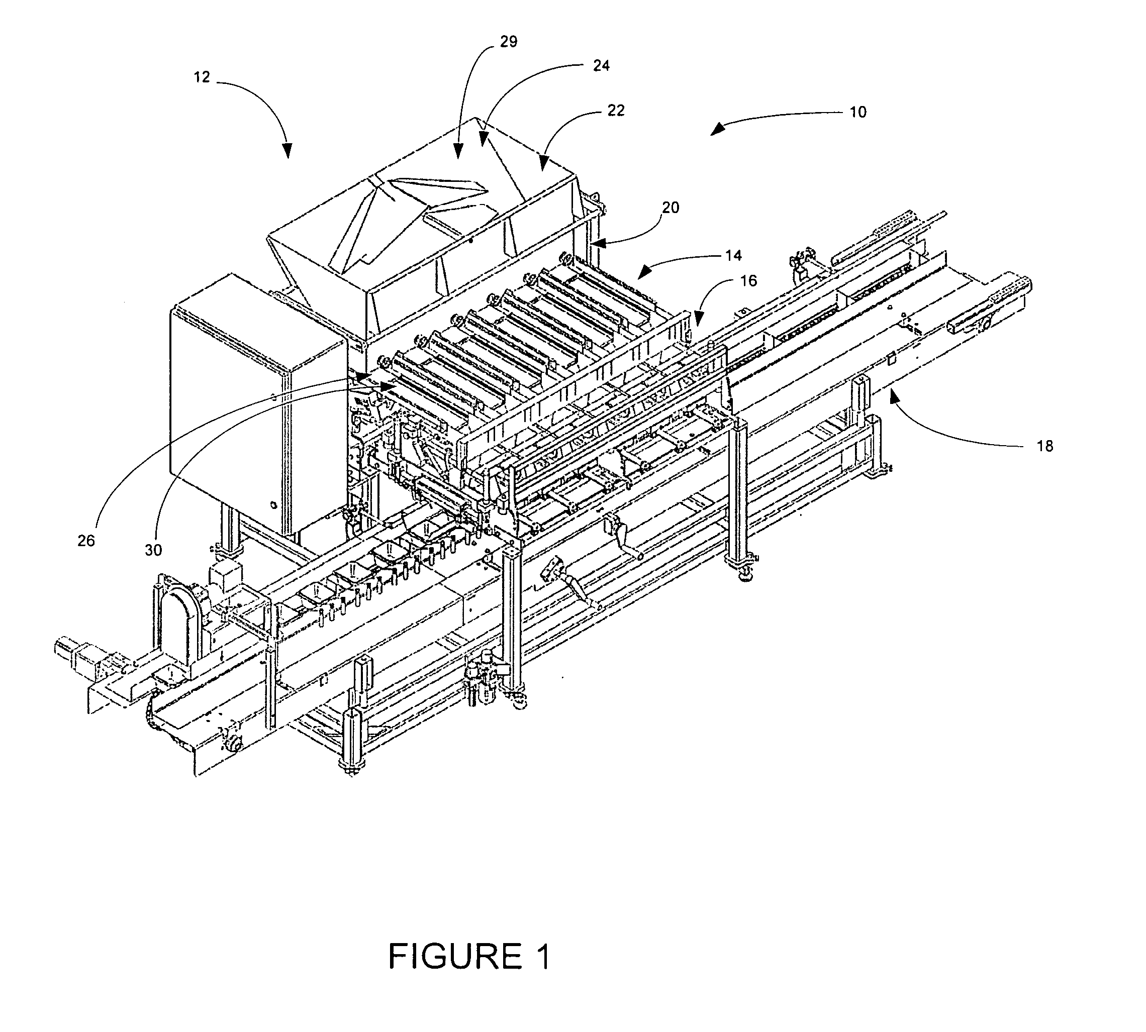
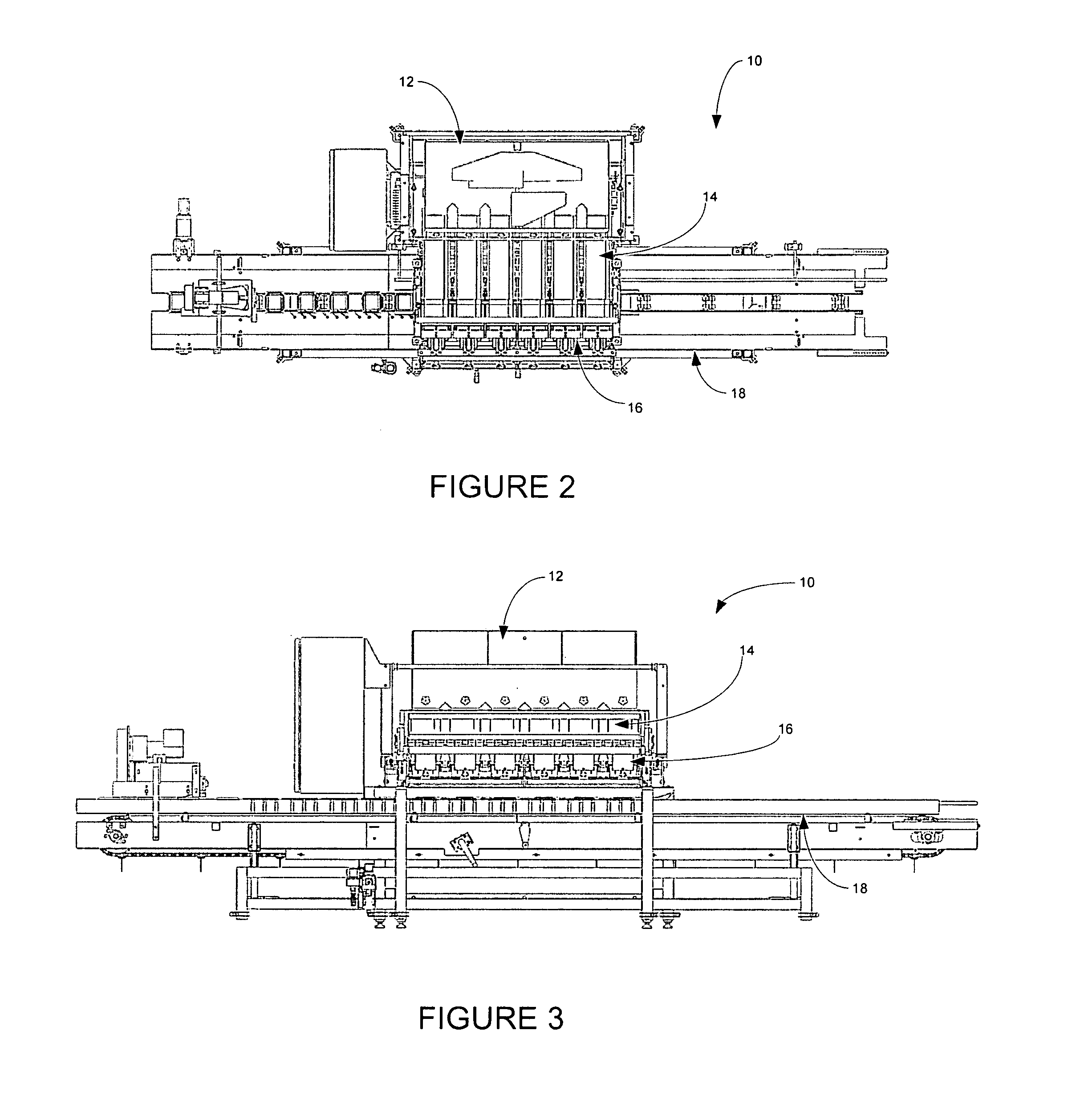
[0036]Referring now to the drawings and in particular to FIG. 1, the weight filling device for small objects is shown generally at 10. The device comprises a hopper 12, a vibrating feeder assembly 14, chute assembly 16 and package conveyor assembly 18. The weight filling device 10 is configur...


PUM


Abstract

A weight filling device for filling small objects comprising a vibrating feed assembly, at least two bins in a side by side orientation, and a chute assembly. The feed assembly includes feed stations having a feed tray with a large feed portion and a small feed portion in a side by side orientation, either integrally formed along a part or all of the length thereof, and each extending to a distal end thereof and vibrating at a predetermined frequency. The bins are positioned so as to be placeable in communication with the distal end of the at least one feed tray. The chute assembly is positioned below the distal end of the at least one feed tray, and has at least one directing chute station having a large feed selector positioned below the large feed portion of the feed tray and a small feed selector positioned below the small feed portion of the feed tray. The large feed selector and the small feed selector are independently pivotable relative to each other between a first position and a second position to direct small objects into the proper bin. The frame for holding the containers to be filled is also vertically adjustable.

Description

BACKGROUND OF THE DISCLOSURE[0001]1. Field of the Disclosure[0002]The disclosure relates in general to filling equipment that typically fills by weight, and more particularly, to weight filling equipment for small objects, such as, for example, berries. It will be understood that the invention is not limited to the filling of any particular small objects, but that berries are exemplary in nature.[0003]2. Background Art[0004]The filling of containers with small objects, such as blueberries, and the like, is known in the art. Typically, the small objects (also referred to herein as product) are directed from a bulk storage member, such as a hopper, through various mechanisms that fill the containers by weight. Of course, the productivity of the overall filling equipment is gauged by how quickly the product can be gathered to a particular weight and then dropped into a container. Thus, such equipment operates substantially continuously.[0005]Among other problems, it is often difficult ...

Claims


Application Information

Patent Timeline
IPC IPC(8): B07B1/32
CPCB65B1/08B65B1/32B65B59/00B65B37/02B65B37/04B65B25/04Y10S209/92Y10S209/925B65B59/003
Inventor MIEDEMA, RANDYMIEDEMA, JEFFSCHEPEL, DENNYMIEDEMA, MIKE
Owner A & B PACKING EQUIP INC
Why Eureka
Try Eureka