
microsatellite comprising a propulsion module and an imaging device

Inactive Publication Date: 2011-10-06
MANZONI GIULIO
View PDF4 Cites 26 Cited by
  • Summary
  • Abstract
  • Description
  • Claims
  • Application Information

AI Technical Summary

Benefits of technology

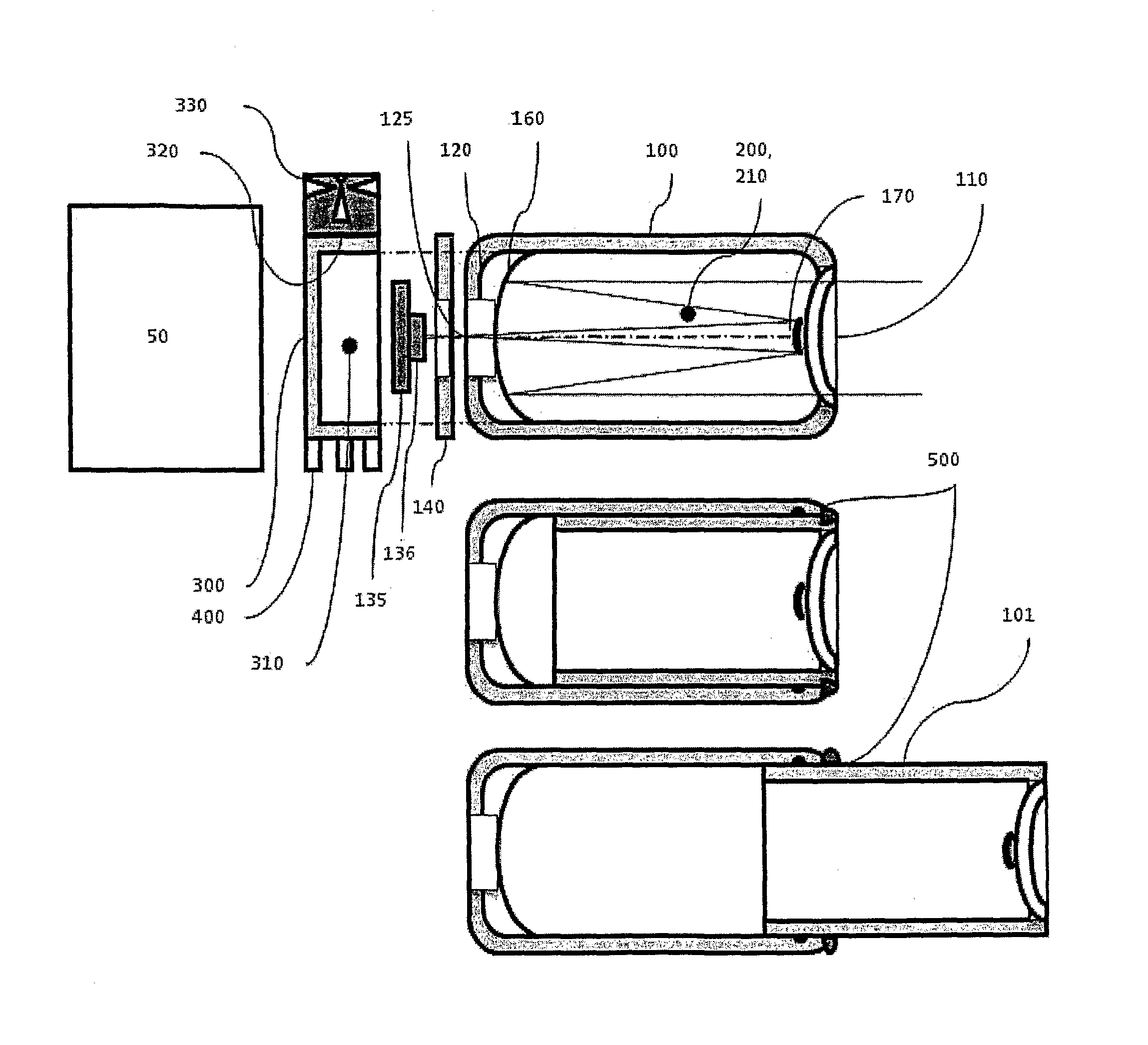
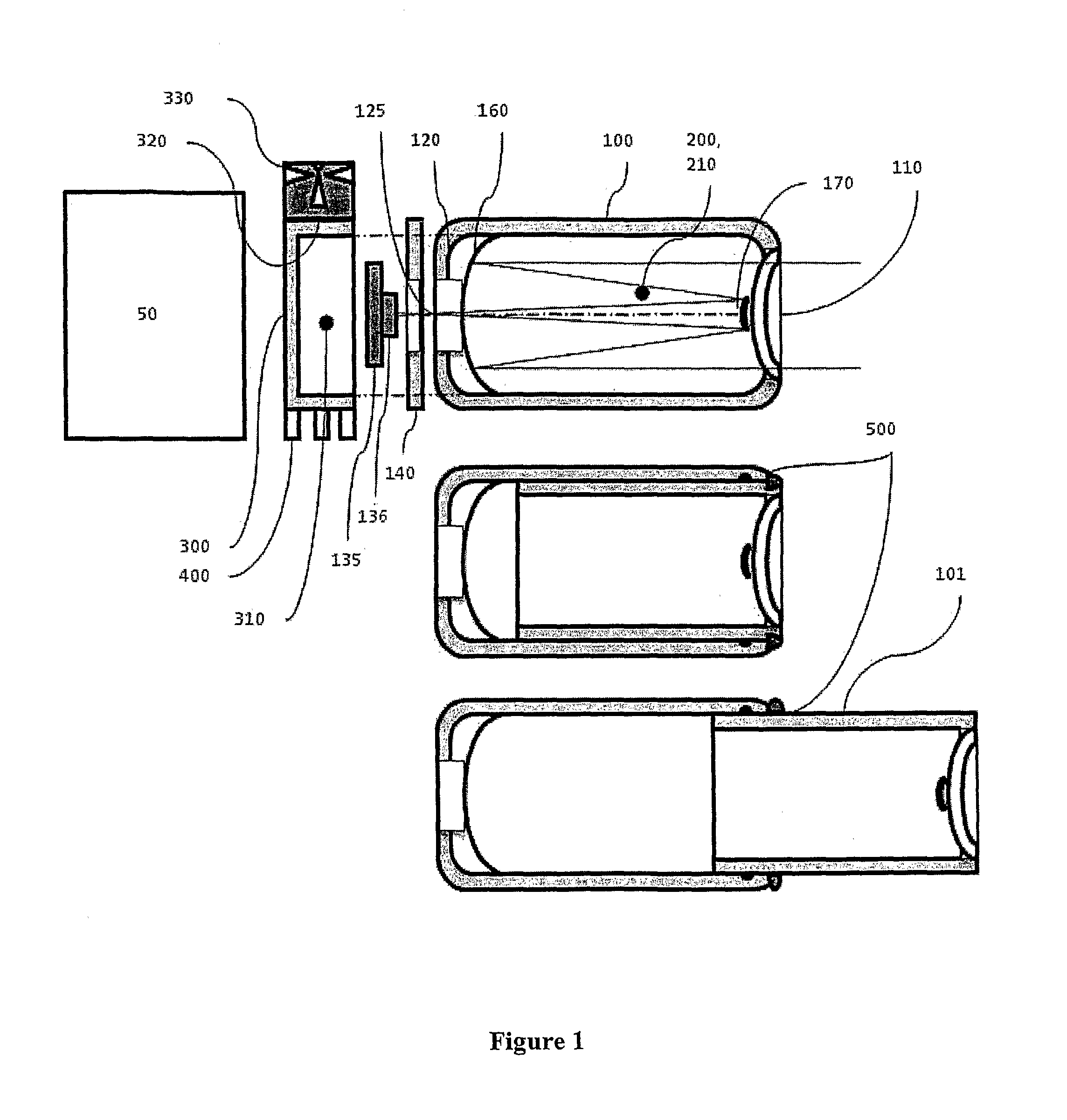
[0014]In one embodiment, the present invention may combine optical and propellant containment systems in order to share efficiently volumes and structures. For this embodiment it is only required that the propellant material is sufficiently transparent to the electromagnetic waves that need to be collected by the detector sensor, the propellant material refraction properties are negligible or can be taken in to account in the design of the optical system and the structure can withstand the pressure of the propellant with negligible or controllable deformation.

Problems solved by technology

However, this requires precise knowledge and control of the relative position of the spacecraft.
Reaction wheels, gyroscopes and other “internal systems” are ineffective to control relative positions of spacecraft; the only useful systems are based on the action-reaction principle thereby requiring ejection of mass from the spacecraft to generate the needed thrust.
Independently on the containment method and propulsion principle, the size of the container ultimately limits the maneuvering lifetime and therefore the usability of the imaging spacecrafts.
Such separate strong structures increase the total mass of the spacecraft and ultimately their manufacturing and launch costs.

Method used


Image

  •  microsatellite comprising a propulsion module and an imaging device
  •  microsatellite comprising a propulsion module and an imaging device
  •  microsatellite comprising a propulsion module and an imaging device

Examples


Embodiment Construction

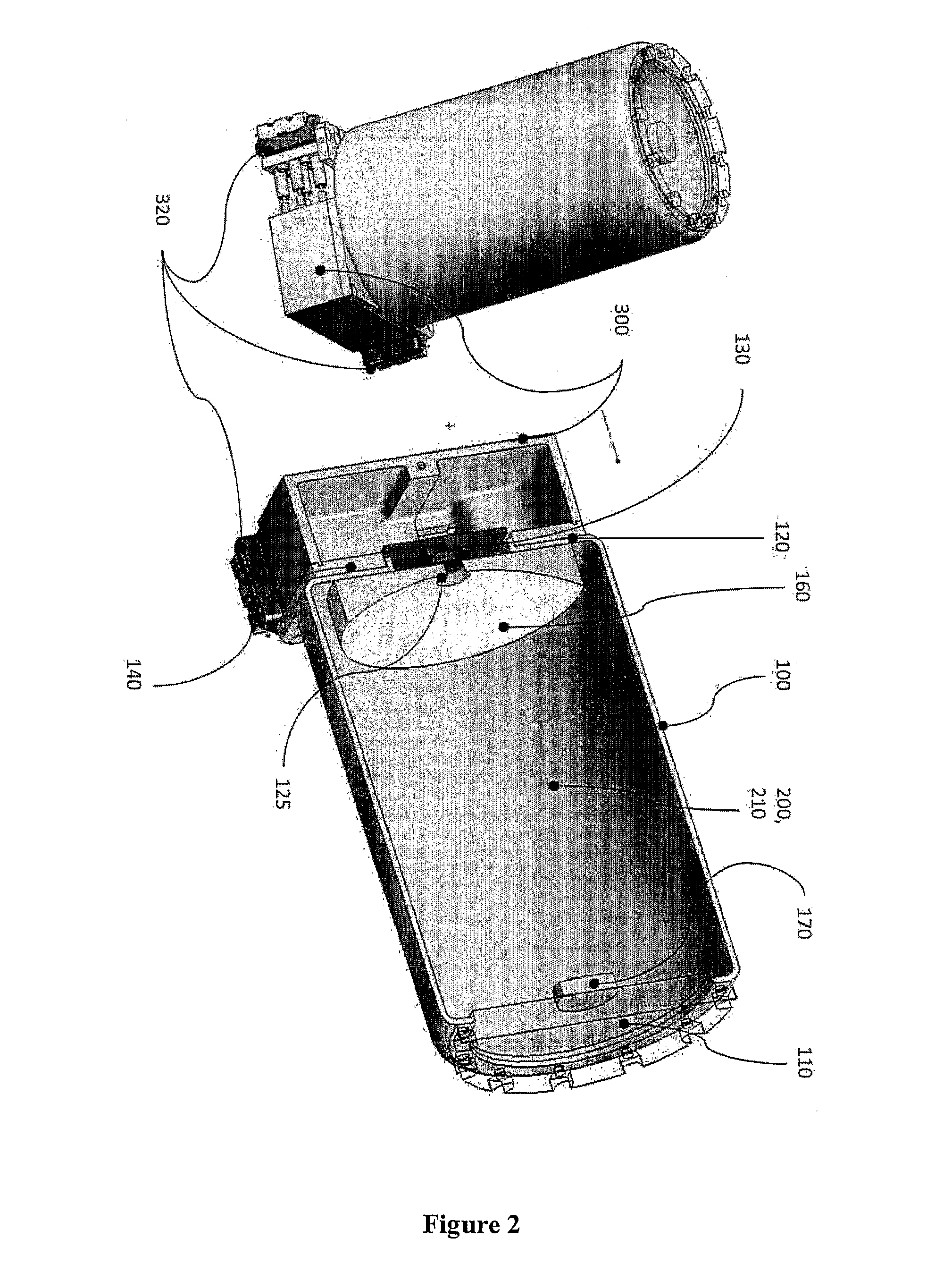
[0049]The invention involves a vehicle moving through space, such as a microsatellite traveling in an orbital path. The microsatellite according to the embodiment of FIGS. 1 and 2 includes an optical chamber, or tube 100 closed at one side by an optically transparent window 110 and at the other side by a flange 120 that allows for the placement of an optical detector 130 in correspondence with an opening 125. The window 110 can also be conveniently shaped as a lens to perform a focusing or correction function in combination with the other lenses or mirrors that combine the optical system. The window 110 has at least the function of closing the tube 100 also with the help of a gasket 115 so that the optical tube 100 can contain a pressurized fluid 200 to be used as propellant. The opening 125 allows for an optical detector 130 such as a CCD or CMOS to receive the image projected by the optical system of lenses and mirrors on the focal plane. The sensor 130 can be before or behind a c...


PUM


Abstract

A microsatellite comprising a propulsion module for moving and / or pointing said microsatellite and an imaging device (100) mounted to said propulsion module. Furthermore there is a fuel supply (210) located within said imaging device (100).

Description

[0001]The invention relates to systems, modules and methods for the use of vehicles, such as those used for orbiting microsatellites, and the ancillary devices used therewith.BACKGROUND OF THE INVENTION[0002]Imaging from Space to Earth or other Space targets rely on the use of spacecraft equipped with cameras or telescopes using refractive or reflective lenses and sensor, detectors and attitude control devices such as thrusters, reaction wheels, gyroscopes to point such optical systems in the desired direction. Using more than one of such spacecrafts imaging the same target it may be possible to achieve a resolution higher than the one of each single optic. However, this requires precise knowledge and control of the relative position of the spacecraft.[0003]Reaction wheels, gyroscopes and other “internal systems” are ineffective to control relative positions of spacecraft; the only useful systems are based on the action-reaction principle thereby requiring ejection of mass from the ...

Claims


Application Information

Patent Timeline
IPC IPC(8): B64G1/10B64G1/26B64G1/36B64G1/40B64G1/66F16K31/02
CPCB64G1/1021F02K99/00B64G1/402B64G1/26F02K9/605B64G1/1028B64G1/66
Inventor MANZONI, GIULIO
Owner MANZONI GIULIO
Learn More