Brake control system

a technology of brake control and control system, applied in the direction of braking system, analogue process for specific applications, instruments, etc., can solve the problems of cumbersome control, complicated calculations, and difficulty in providing brake force according to the amount of brake operation of the driver

Active Publication Date: 2011-10-06
HITACHI ASTEMO LTD
View PDF6 Cites 33 Cited by
  • Summary
  • Abstract
  • Description
  • Claims
  • Application Information

AI Technical Summary

Benefits of technology

The brake control system described in this patent allows for effective brake controls in a variety of situations.

Problems solved by technology

The present invention aims to provide a brake control system that can appropriately perform various controls, such as boost control, brake assist control, anti-lock control, and vehicle stability control. The current control method based on a relative displacement between an input member and a primary piston is complicated and cannot provide an excellent brake operation feeling. Therefore, the objective of the invention is to simplify the control method and provide a better brake operation feeling.

Method used


Image

  • Brake control system
  • Brake control system
  • Brake control system

Examples


Embodiment Construction

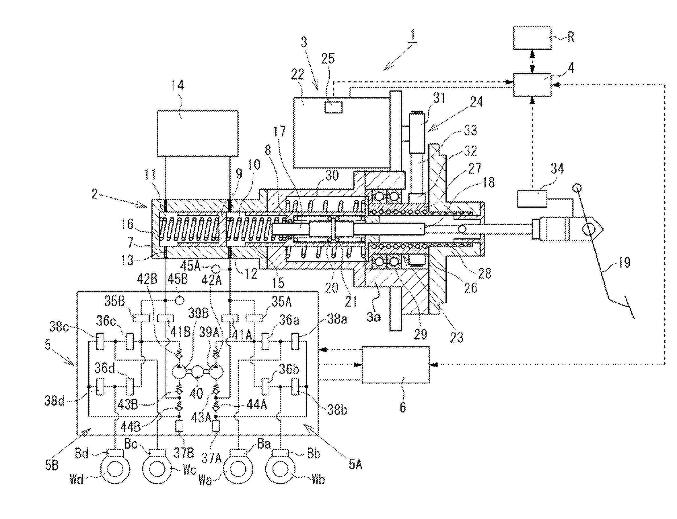
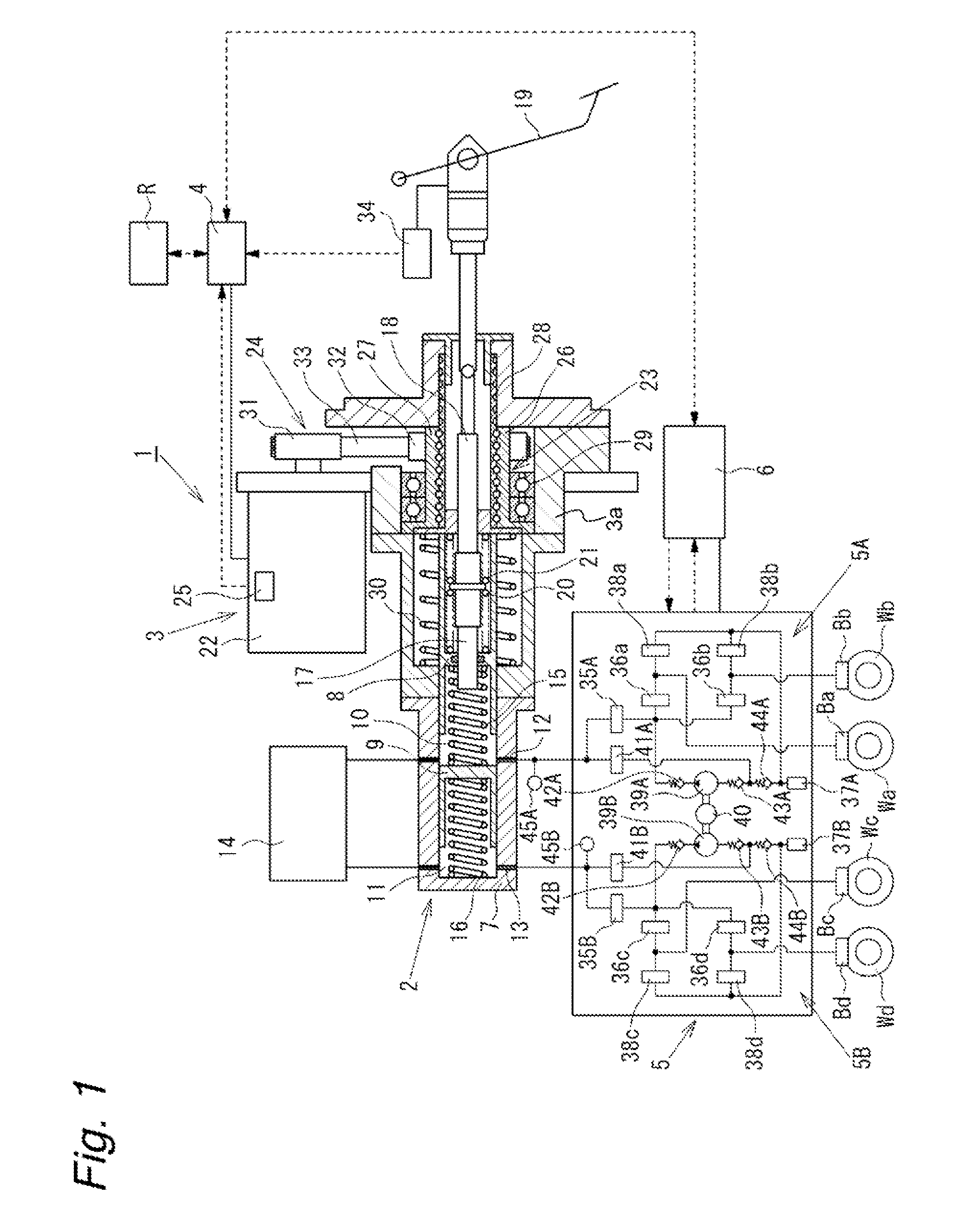
[0027]Hereinafter, an embodiment of the present invention will be described in details with reference to the accompanying drawings. FIG. 1 shows an overall configuration of a brake control system according to the present embodiment. As shown in FIG. 1, a brake control system 1 according to the present embodiment is applied to a brake apparatus of a motor vehicle, and functions to control brake forces applied to four wheels, a front left wheel Wa, a rear right wheel Wb, a front right wheel Wc, and a rear left wheel Wd. The brake control system 1 includes a master cylinder 2, a master pressure control mechanism 3 integrally installed to the master cylinder 2, a master pressure control unit 4 configured to control an operation of the master pressure control mechanism 3, a wheel pressure control mechanism 5 configured to control hydraulic pressures supplied to wheel cylinders of hydraulic brakes Ba, Bb, Bc, and Bd attached to the wheels Wa, Wb, Wc, and Wd, and a wheel pressure control u...


PUM


Abstract

An object of the present invention is to simplify a control during regenerative cooperation in a brake control system generating a hydraulic pressure in a master cylinder by displacing a piston with use of an electric actuator according an operation amount of a brake pedal. The brake control system displaces the primary piston 8 by controlling an operation of the electric motor 22 by a master pressure control unit 4 according to the operation amount Xop of the brake pedal 19, thereby generating a hydraulic pressure in the master cylinder 2 to supply it to wheel cylinders Ba to Bd. The master pressure control unit 4 sets a target relative displacement ΔXT between an input piston 17 and the primary piston 8 and a target hydraulic pressure PT in the master cylinder 2, and appropriately switch which is used to control a brake force. During regenerative cooperation, the master pressure control unit 4 selects the control with use of the target hydraulic pressure PT, which enables easy execution of a hydraulic pressure control including a subtraction of the hydraulic pressure corresponding to a brake effect from the regenerative cooperation.

Description


Claims


Application Information

Patent Timeline
Owner HITACHI ASTEMO LTD
Why Eureka
Try Eureka