
Battery saver

a battery and saver technology, applied in the direction of contact members penetrating/cutting insulation/cable strands, emergency power supply arrangements, safety/protection circuits, etc., can solve the cost and inconvenience of premature replacement of batteries, and the lack of a commercially available shut-off device with a reliably simple design

Active Publication Date: 2011-10-06
MCPHERSON JODY
View PDF1 Cites 3 Cited by
  • Summary
  • Abstract
  • Description
  • Claims
  • Application Information

AI Technical Summary

Benefits of technology

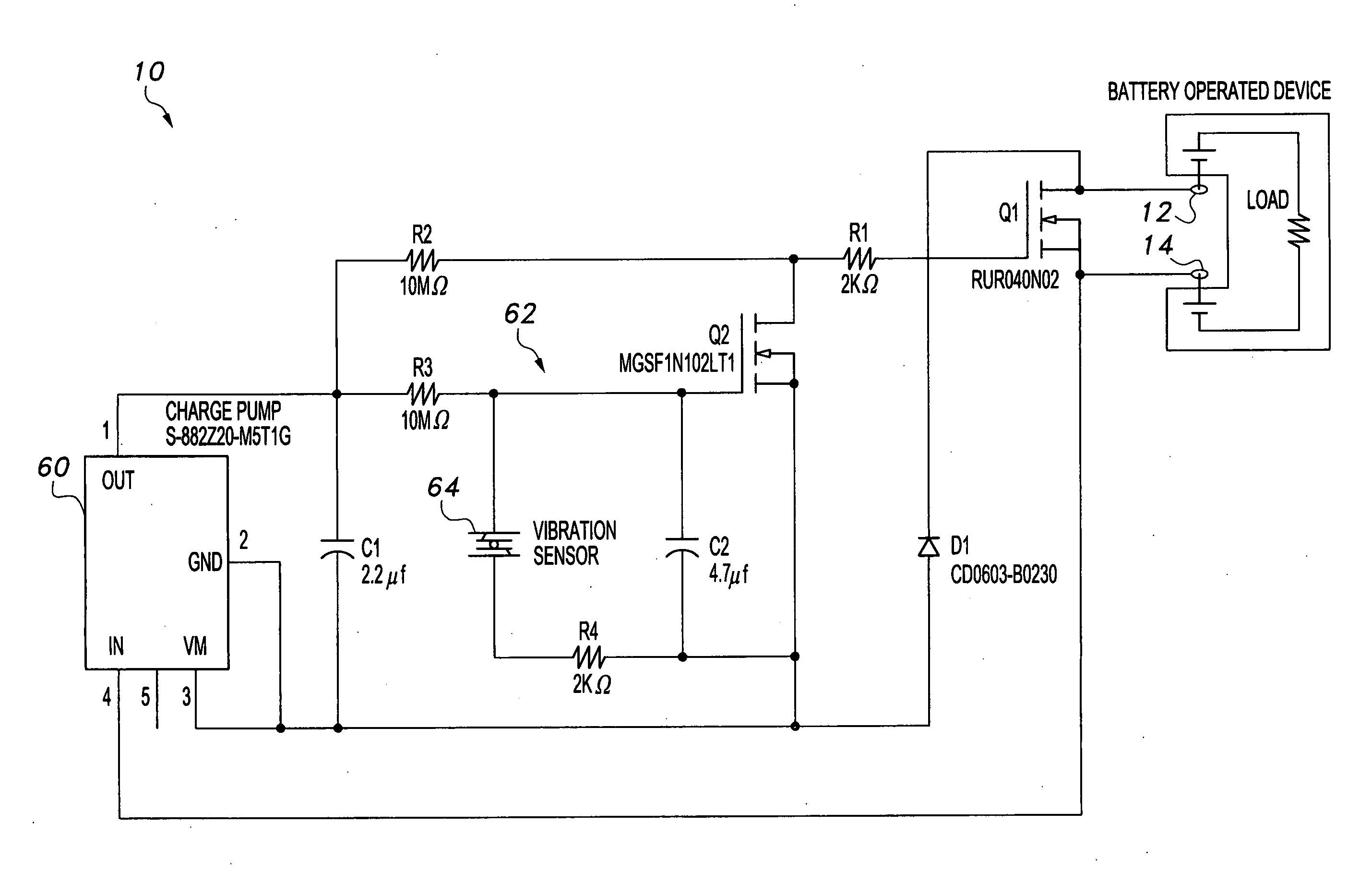
[0007]The battery saver includes a charge pump connected to a control switch to provide a time-hysteretic threshold feature wherein it takes a longer, elapsed time threshold to activate the control switch than it does to deactivate the control switch. Control switch output is connected to a main switch wherein activation of the control switch opens the main switch to de-energize a battery-powered device's battery circuit. Control switch deactivation closes the main switch, which energizes the battery circuit of the battery-powered device.
[0008]A quick elapsed time threshold allows a vibration sensor, which indicates continuing use of the battery-powered device, to instantaneously deactivate the control switch when vibrations are sensed. When the vibration sensor no longer senses motion in the device, a longer elapsed time threshold is triggered in which the charge pump slowly ramps up current to activate the control switch to turn the battery-operated device off.

Problems solved by technology

A known problem with battery-powered devices, such as flashlights, wireless microphones, and the like, is that they are often inadvertently left on after use, resulting in the cost and inconvenience of premature replacement of batteries.
However, there does not appear to be a commercially available shut-off device that has a reliably simple design and that is adaptable to a wide range of products.

Method used


Image

  • Battery saver
  • Battery saver
  • Battery saver

Examples


Embodiment Construction

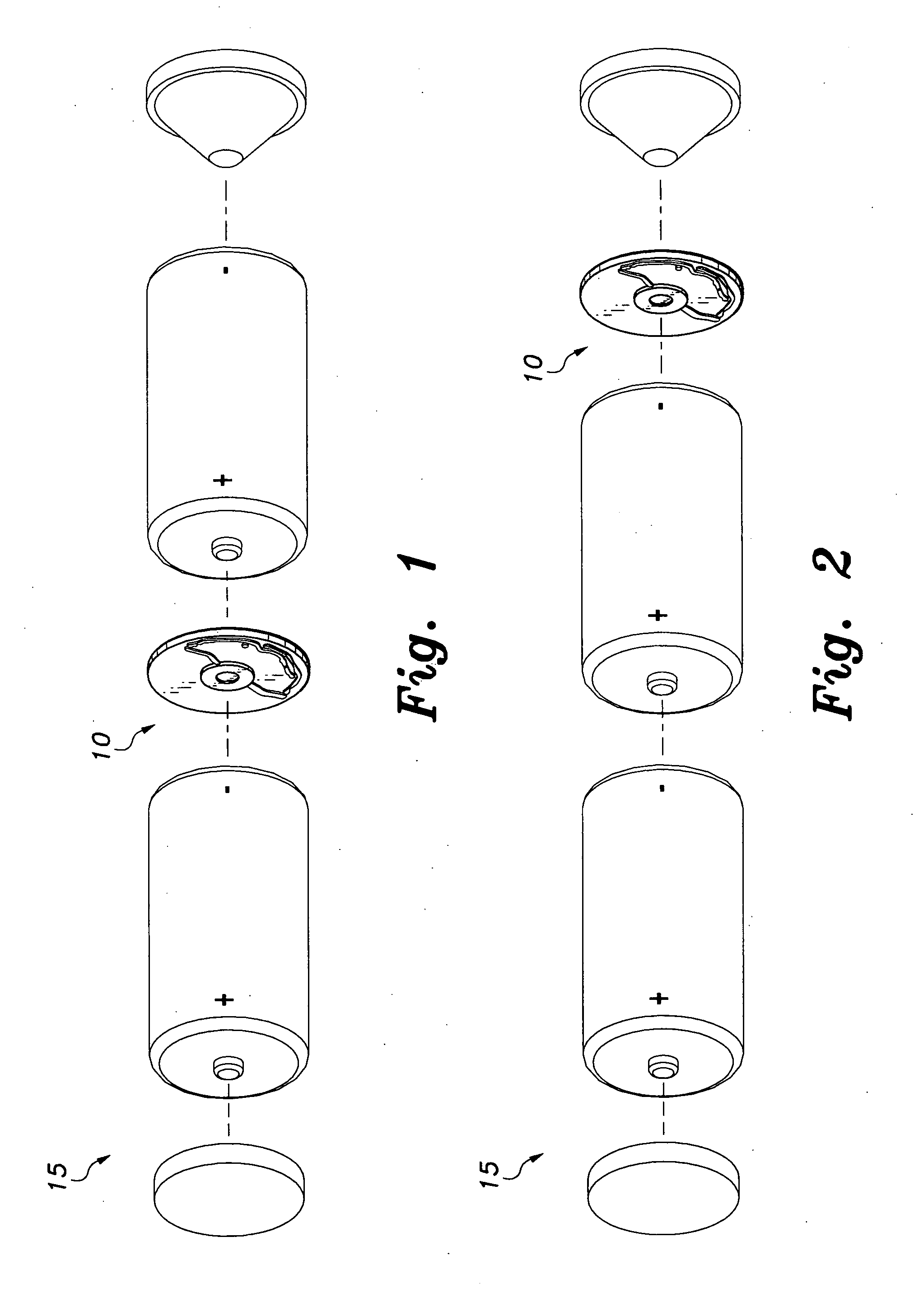
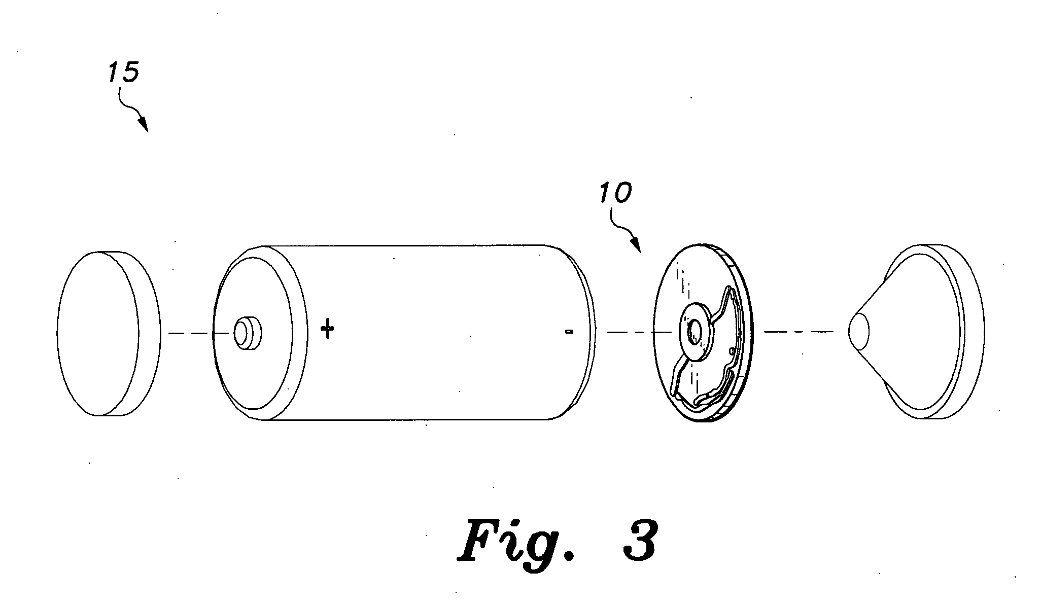
[0020]The battery saver 10 is configured as a thin disc adapted for insertion in a battery housing between a load device and a battery powering the load device. The battery saver 10 is manufactured in several sizes to enable compatibility with a variety of battery sizes and the corresponding devices they power. The battery saver 10 includes a vibration sensor 64 (FIG. 6) that allows the inventive battery saver 10 to pass the battery power to the battery operated device so that it will not turn off as long as the battery-operated device is in motion. The installed battery saver 10 shuts off power to the battery-operated device when the device has been motionless for a predetermined time period. If the battery-operated device has turned off due to being motionless and is reintroduced to motion, the battery saver 10 will turn the battery-operated device back on. Thus, the battery saver 10 prolongs battery life by automatically shutting down a motionless battery operated device.

[0021]As...


PUM


Abstract

The battery saver includes a charge pump connected to a control switch to provide a time-hysteretic threshold feature wherein it takes a longer, elapsed time threshold to activate the control switch than it does to deactivate the control switch. Control switch output is connected to a main switch wherein activation of the control switch opens the main switch to de-energize a battery-powered device's battery circuit. Control switch deactivation closes the main switch, which energizes the battery circuit of the battery-powered device. A quick elapsed time threshold allows a vibration sensor, which indicates continuing use of the battery-powered device, to instantaneously deactivate the control switch when vibrations are sensed. When the vibration sensor no longer senses motion in the device, a longer elapsed time threshold is triggered in which the charge pump slowly ramps up current to activate the control switch to turn the battery-operated device off.

Description

BACKGROUND OF THE INVENTION[0001]1. Field of the Invention[0002]The present invention relates to devices for conserving energy, and particularly to a battery saver that includes a switch that opens a battery circuit of a device after the device has been motionless for a predetermined time period.[0003]2. Description of the Related Art[0004]A known problem with battery-powered devices, such as flashlights, wireless microphones, and the like, is that they are often inadvertently left on after use, resulting in the cost and inconvenience of premature replacement of batteries. To avoid this, some battery-powered devices include timers as part of the circuitry that shut the devices down, or initiate a standby mode, after a predetermined period of non-use.[0005]There is even a product that has a plurality of circuit modules to perform the shut down task. However, there does not appear to be a commercially available shut-off device that has a reliably simple design and that is adaptable to...

Claims


Application Information

Patent Timeline
Patent Type & Authority Applications(United States)
IPC IPC(8): H02J7/06H02J7/04
CPCH02J7/0031H02J2007/0067H02J9/005H02J7/007188
Inventor MCPHERSON, JODY
Owner MCPHERSON JODY
Learn More