Current sensor

a current sensor and sensor technology, applied in the field of current sensors, can solve the problems of reducing reliability and affecting the operation of current sensors, and achieve the effect of preventing the reduction of reliability and reducing the effect of noise on the capacitor

Active Publication Date: 2011-10-06
DENSO CORP
View PDF0 Cites 18 Cited by
  • Summary
  • Abstract
  • Description
  • Claims
  • Application Information

AI Technical Summary

Benefits of technology

[0007]An embodiment provides a current sensor in which the effects of noise on a capacitor can be reduced, whereby reliability thereof is prevented from decreasing due to malfunction thereof.
[0008]As an aspect of the embodiment, a current sensor, which senses current passing through a harness via a terminal of a battery, includes: a resistor through which current passes; a current sensing circuit which measures the current passing through the resistor based on a potential difference between two positions along the direction in which current is passed through the resistor; a power supply circuit which supplies power to the current sensing circuit; and at least one capacitor which is connected to at least one of an input terminal and an output terminal of the power supply circuit to smooth input / output voltage. The resistor includes a flat energizing path, and the capacitor is disposed in an area other than a plane of projection of the energizing path on a board on which the current sensing circuit and the power supply circuit are mounted.

Problems solved by technology

Accordingly, the current sensor is subject to noise and is likely to decrease reliability due to malfunction thereof.

Method used


Image

  • Current sensor
  • Current sensor
  • Current sensor

Examples


Embodiment Construction

[0016]With reference to the accompanying drawings, hereinafter is described an embodiment of a current sensor. The current sensor of the embodiment is mounted on, for example, a vehicular lead battery and is used for sensing the charge / discharge current of the battery.

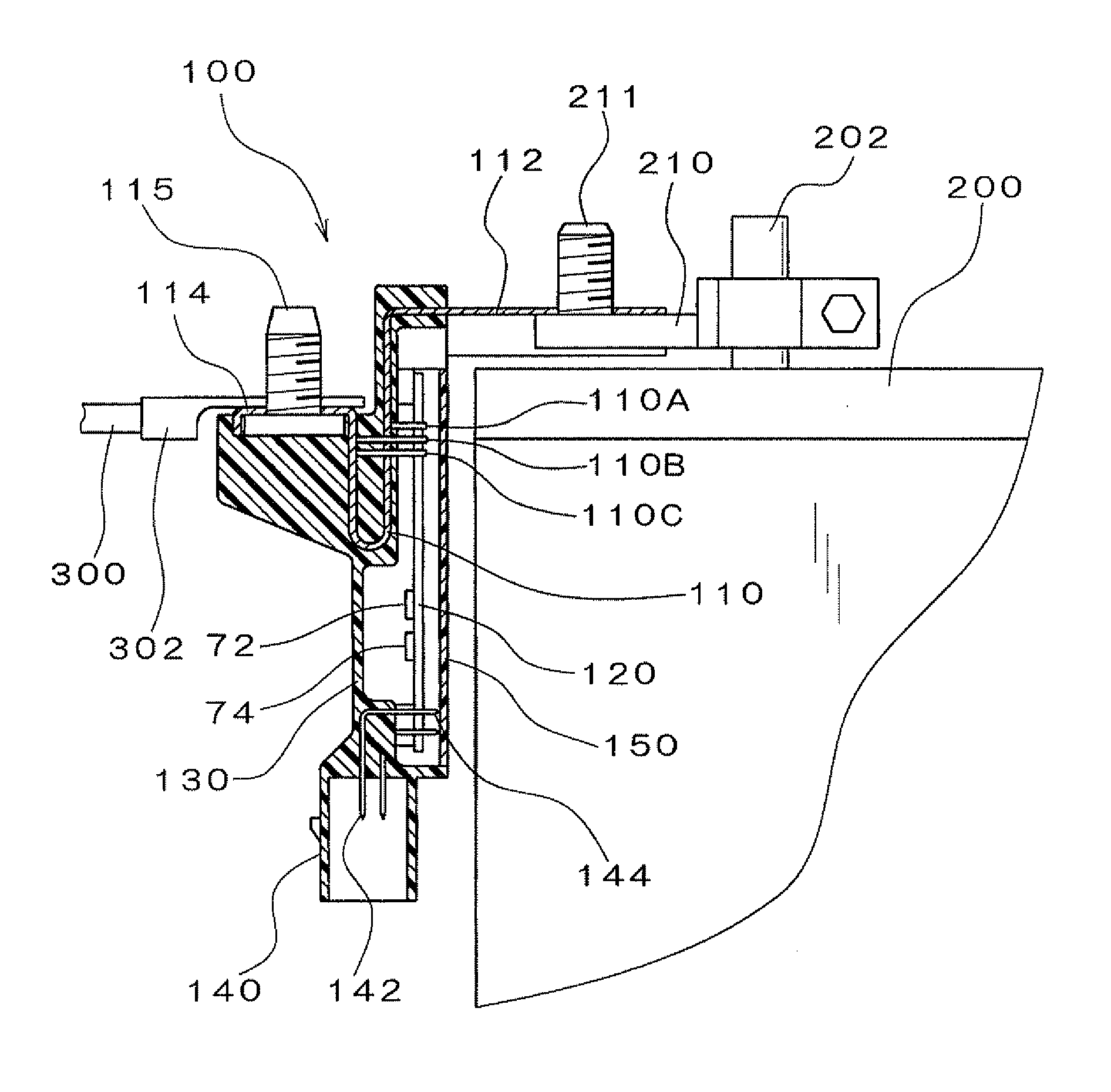
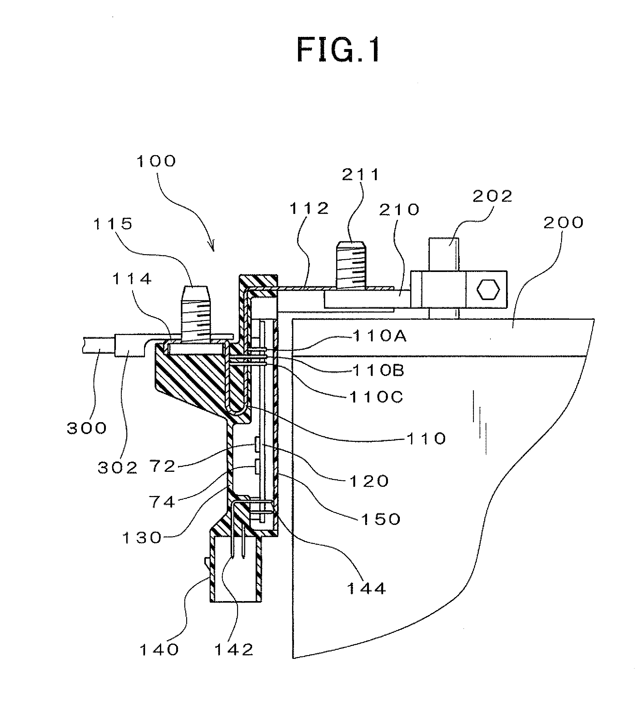
[0017]FIG. 1 is a cross-sectional view illustrating a configuration of a current sensor 100 according to the embodiment. FIG. 1 shows a state where the current sensor 100 is attached to a battery of a motor vehicle. FIG. 2 is a side view illustrating the current sensor 100 and FIG. 3 is a perspective view illustrating the current sensor 100.

[0018]As shown in these figures, the current sensor 100 of the present embodiment includes a bus bar 110, a circuit board 120, a case 130, a connector 140 and a cover 150. The bus bar 110 is made of an electrically conductive material and serves as a resistor (shunt resistor). The circuit board 120 is mounted with a current sensing circuit which measures current passing through the ...


PUM


Abstract

A current sensor, which senses current passing through a harness via a terminal of a battery, includes a resistor through which current passes, a current sensing circuit which measures the current passing through the resistor based on a potential difference between two positions along the direction in which current is passed through the resistor, a power supply circuit which supplies power to the current sensing circuit, and at least one capacitor which is connected to at least one of an input terminal and an output terminal of the power supply circuit to smooth input / output voltage. The resistor includes a flat energizing path, and the capacitor is disposed in an area other than a plane of projection of the energizing path on a board on which the current sensing circuit and the power supply circuit are mounted.

Description

CROSS-REFERENCE TO RELATED APPLICATION[0001]This application is based on and claims the benefit of priority from earlier Japanese Patent Application No. 2010-41590 filed Feb. 26, 2010, the description of which is incorporated herein by reference.BACKGROUND[0002]1. Technical Field[0003]The present invention relates to a current sensor that senses charge / discharge current of a battery installed such as in a passenger car or a truck.[0004]2. Related Art[0005]Conventionally, current sensors have been known in which a current sensing circuit housed in a case is provided at a middle portion in the longitudinal direction of a flat bus bar. In JP-A-2008-39571, a current sensing circuit is disposed so as to be opposed to a shunt resistor. The current sensing circuit senses the voltage across the shunt resistor to measure the charge / discharge current of a battery.[0006]As described above, the current sensor disclosed in JP-A-2008-39571 has the current sensing circuit disposed so as to be oppo...

Claims


Application Information

Patent Timeline
Patent Type & Authority Applications(United States)
IPC IPC(8): G01R19/00
CPCG01R31/3696G01R1/203G01R31/364
Inventor OZAWA, JYUN
Owner DENSO CORP
Why Eureka
Try Eureka