Ink-jet recording apparatus

Active Publication Date: 2011-10-06
BROTHER KOGYO KK
View PDF0 Cites 2 Cited by
  • Summary
  • Abstract
  • Description
  • Claims
  • Application Information

AI Technical Summary

Benefits of technology

[0009]An object of the present invention is to provide an ink jet recording apparatus which is provided with a protective member for preventing the recording paper from being brought in contact with a jetting surface of an ink-jet head and which simultaneously makes it possible to prevent a carriage from being moved in the separating direction to make separation from a transport surface for the recording paper by the force allowed to act on the protective member from the recording paper.
[0019]According to the inkjet recording apparatus concerning the first aspect of the present invention, the movement of the second carriage in relation to the third direction is regulated by the regulating member. Therefore, the nearest portion of the protective member, which is provided with respect to the transport surface, is always disposed at a position nearer to the transport surface as compared with the jetting surface. Therefore, even when the medium such as the recording paper or the like is bent or curled in the separating direction to make separation from the transport surface in the third direction, the medium is brought in contact with the protective member which is disposed nearer to the transport surface as compared with the jetting surface in relation to the third direction. Accordingly, it is possible to prevent the recording paper from being brought in contact with the jetting surface.
[0020]Further, in this situation, the second carriage, which is provided with the protective member, is constructed relatively movably in the third direction with respect to the first carriage, and the movement in relation to the third direction is regulated by the regulating member so that the nearest portion of the protective member, which is provided with respect to the transport surface, is always disposed nearer to the transport surface as compared with the jetting surface in relation to the third direction. Therefore, when the medium such as the recording paper or the like is bent in the separating direction to make separation from the transport surface in the third direction, and the protective member is pressed in this direction, then the second carriage is relatively moved in the separating direction to make separation from the transport surface in the third direction with respect to the first carriage. In another situation, the movement of the second carriage is regulated by the regulating member, and the second carriage is not moved. In any case thereof, the first carriage can be prevented from being moved in the separating direction to make separation from the transport surface in the third direction, which would be otherwise moved by the force of the recording paper to press the protective member.

Problems solved by technology

If the carriage is moved in the separating direction to make separation from the transport surface for the recording paper, it is feared that the meniscus of the nozzle may be destroyed by the acceleration brought about when the carriage is moved in the separating direction to make separation from the transport surface and / or that the distance between the jetting surface and the recording paper may be varied or fluctuated to deteriorate the printing quality.
If the velocity of movement of the carriage is varied or fluctuated, it is feared that the printing quality may be lowered.

Method used


Image

  • Ink-jet recording apparatus
  • Ink-jet recording apparatus
  • Ink-jet recording apparatus

Examples


first modified embodiment

[0068]In a first modified embodiment, as shown in FIG. 5, a connecting section 32 of a frame 21 is prolonged or elongated in the left-right direction as compared with the embodiment described above, and spaces are provided between the first carriage 4 and two support sections 31 of the frame 21. Compression springs 41 (biasing members), which extend in the up-down direction, are arranged in the spaces respectively.

[0069]The lower ends of the compression springs 41 are attached to spring attachment sections 42 provided on the side surfaces in relation to the left-right direction of the first carriage 4. Further, the upper ends of the compression springs 41 are attached to spring attachment sections 43 provided on the side surfaces of the support sections 31 disposed on the side of the first carriage 4. Accordingly, the second carriage 9 is biased by the compression springs 41 upwardly (in the separating direction to make separation from the transport surface 7a in the third direction...

second modified embodiment

[0076]In the embodiment described above, the pair of rollers 22, which are arranged on the both sides in relation to the left-right direction of the first carriage 4, are provided on the same second carriage 9, and the pair of rollers 22 are connected to one another by the frame 21. However, the present teaching is not limited to such an arrangement.

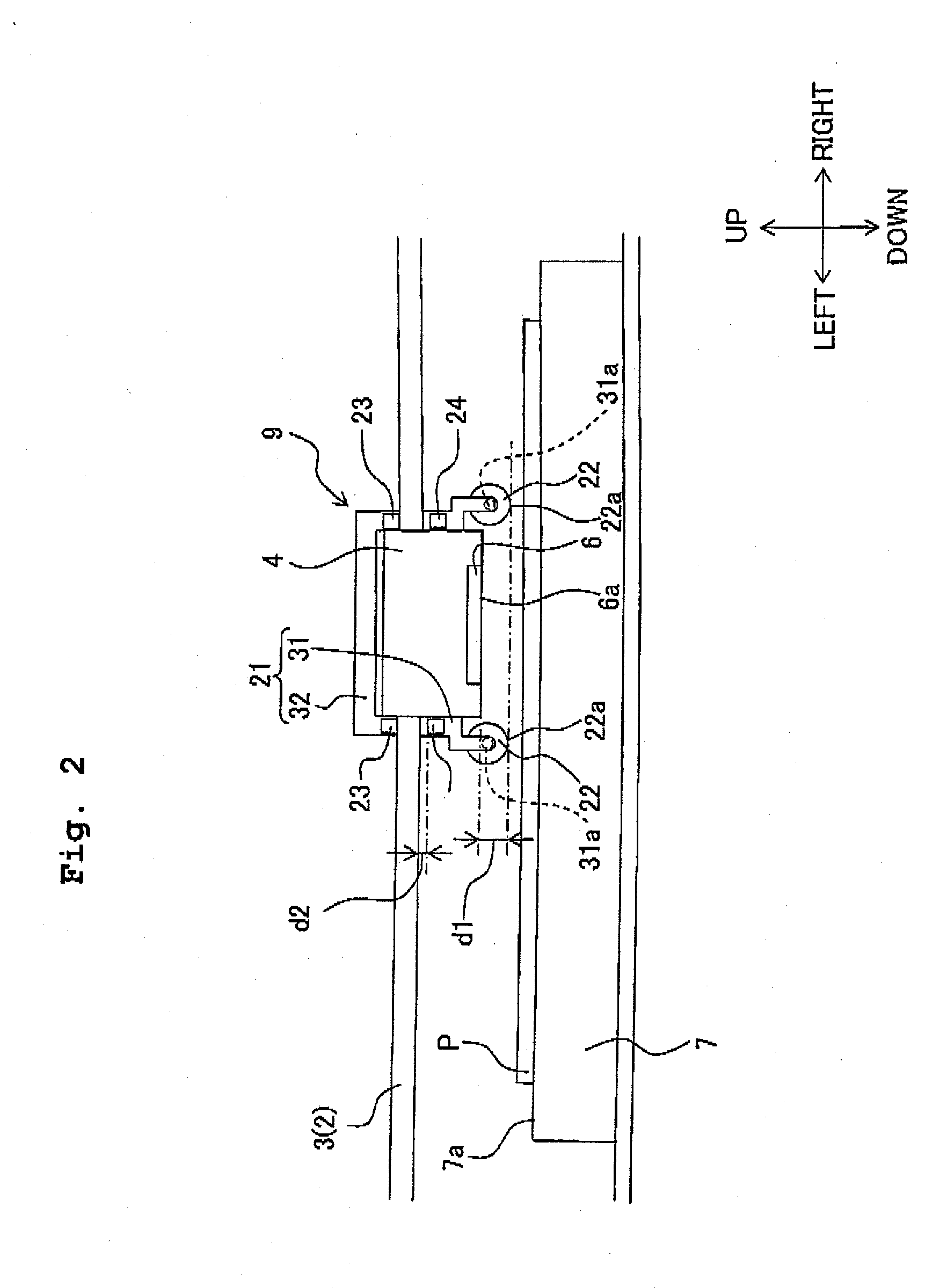
[0077]In a second modified embodiment, as shown in FIG. 6, second carriages 51 are arranged separately on the both sides of the first carriage 4 in relation to the left-right direction. Each of the second carriages 51 is provided with a support member 52 which has approximately the same shape as that of the support section 31 described above (see FIG. 2). Rollers 22 are rotatably supported by shafts 31a of the support members 52. The support members 52 are provided with protrusions 23, 24 at the same or equivalent positions as those of the support sections 31.

[0078]The first carriage 4 is provided with interposing sections 53 at both end...

third modified embodiment

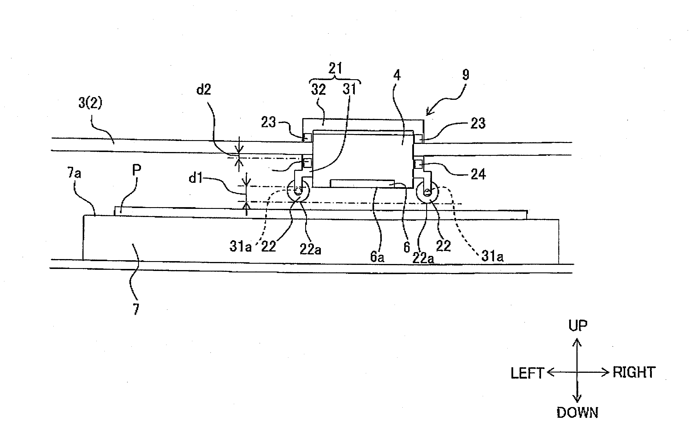
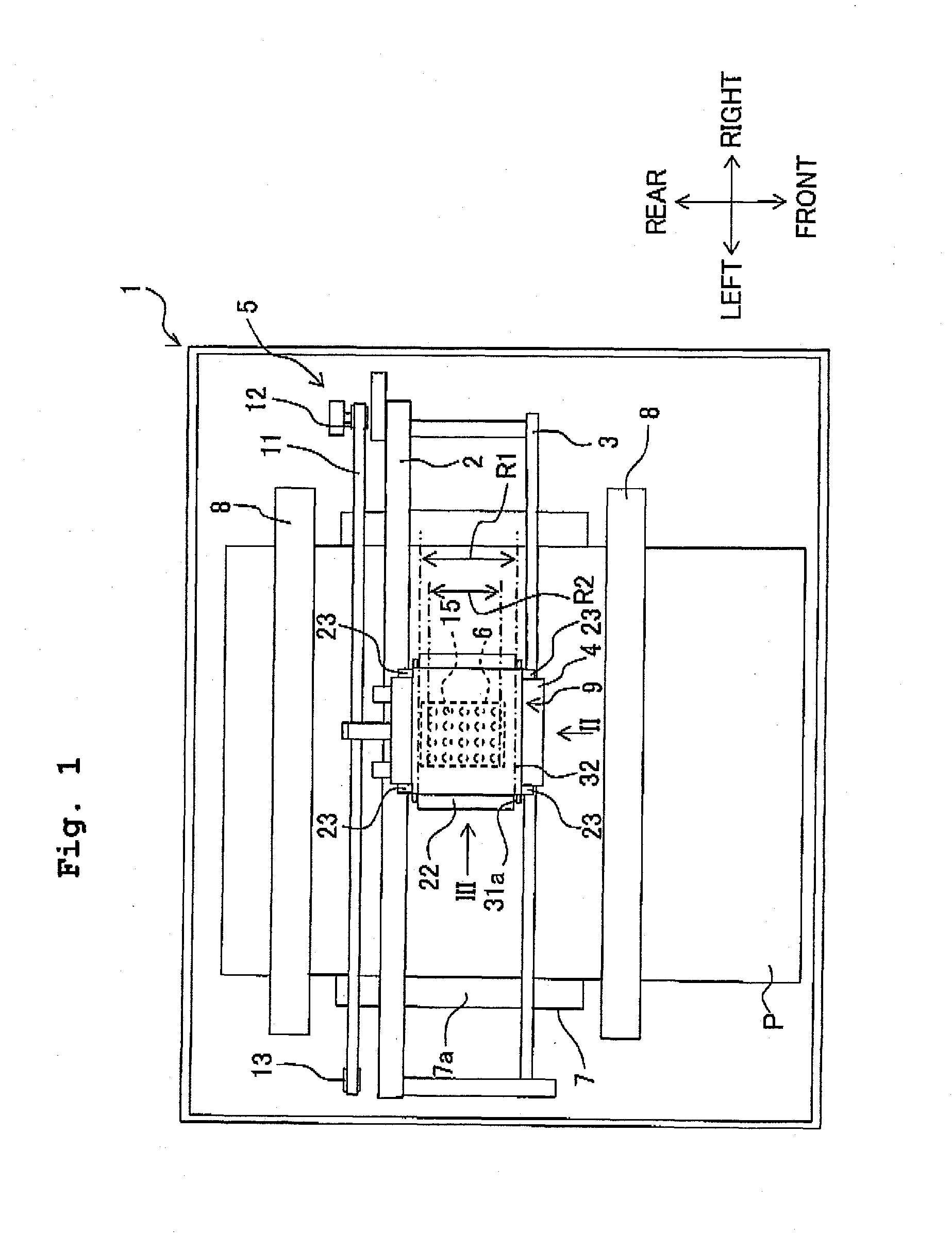
[0080]In the embodiment described above, both of the rollers 22, which are arranged on the both sides in relation to the left-right direction of the first carriage 4, extend over the range R1 which is wider than the range R2 in which the nozzles 15 are arranged, in relation to the front-back direction. However, the present invention is not limited thereto.

[0081]In a third modified embodiment, as shown in FIG. 7, a roller 61 arranged on the left side of the first carriage 4 and a roller 62 arranged on the right side of the first carriage 4 extend over only a range R3 and a range R4 which are narrower than the range R2 in which the nozzles 15 are arranged, in relation to the front-back direction, respectively. However, a range, which is obtained by combining the two ranges R3, R4, is wider than the range R2.

[0082]Also in this case, when the portion of the recording paper P, which is opposed to the nozzles 15, is bent or curled, for example, due to the swelling, the portion is brought ...


PUM


Abstract

An ink-jet recording apparatus is provided, the ink-jet recording apparatus including an ink-jet head, a first carriage on which the ink-jet head is carried, a guide member, a moving mechanism which moves the first carriage along the guide member, a transport mechanism which transports a medium along a transport surface, and a second carriage which is reciprocatively movable while following movement of the first carriage and which is constructed relatively movably in a direction perpendicular to the transport surface with respect to the first carriage. The second carriage has a protective member which protects a jetting surface from the medium and a regulating member which regulates movement of the second carriage in relation to a third direction.

Description

CROSS REFERENCE TO RELATED APPLICATION[0001]The present application claims priority from Japanese Patent Application No. 2010-080492, filed on Mar. 31, 2010, the disclosure of which is incorporated herein by reference in its entirety.BACKGROUND OF THE INVENTION[0002]1. Field of the Invention[0003]The present invention relates to an ink-jet recording apparatus for jetting an ink or inks from nozzles.[0004]2. Description of the Related Art[0005]In an ink-jet printer described in Japanese Patent Application Laid-open No. 7-61078, runners or rollers, which are rotatably supported by shafts extending in a direction perpendicular to a scanning direction, are arranged respectively at both end portions in relation to the scanning direction of a carriage which is reciprocatively movable in the scanning direction and on which a printing head is carried. The recording paper is pressed downwardly by the rollers. Accordingly, the recording paper is prevented from causing the floating-up which wo...

Claims


Application Information

Patent Timeline
IPC IPC(8): B41J23/00
CPCB41J25/3082B41J11/005
Inventor TERADA, KOHEI
Owner BROTHER KOGYO KK
Why Eureka
Try Eureka