
Endosseous screws and orthopaedic device to assist the rigid osteosynthesis of fractures

a technology of endosseous screws and orthopaedic devices, which is applied in the field of orthopaedic devices for the osteosynthesis of fractures, can solve the problems of difficult removal after, recessed screws may be untightened, and endosseous screws are difficult to remove, so as to facilitate the removal of orthopaedic devices and facilitate the insertion of manipulating wrenches

Active Publication Date: 2011-10-06
ORTHOFIX SRL
View PDF10 Cites 2 Cited by
  • Summary
  • Abstract
  • Description
  • Claims
  • Application Information

AI Technical Summary

Benefits of technology

[0014]More in particular, the screw head may be easily inserted into the manipulating wrench, even at an angle, always allowing the transmission of torque between wrench and screw, thus facilitating the removal of the orthopedic device.

Problems solved by technology

Although being advantageous from various points of view, endosseous screws according to the known art have a serious drawback in that they are difficult to remove after complete osteosynthesis (screws with hexagonal recessed cavity), if not impossible to remove (shaft screws).
In fact, whereas shaft screws are totally lacking extraction means once the shaft has been removed, recessed screws may be untightened by inserting the instrument in the same cavity provided for tightening.
But unfortunately, in practice, the extraction hexagonal recessed screws is rarely without complications.
In fact, during osteosynthesis or surgical removal the screw cavity is often occluded or deformed.
In situation such as these the untightening operation is very complicated, or even impossible.
The drawback described above is particularly critical precisely in the case of angular stability plates; the engagement between screws and holes in the plate effectively complicates their extraction.

Method used


Image

  • Endosseous screws and orthopaedic device to assist the rigid osteosynthesis of fractures
  • Endosseous screws and orthopaedic device to assist the rigid osteosynthesis of fractures
  • Endosseous screws and orthopaedic device to assist the rigid osteosynthesis of fractures

Examples


Embodiment Construction

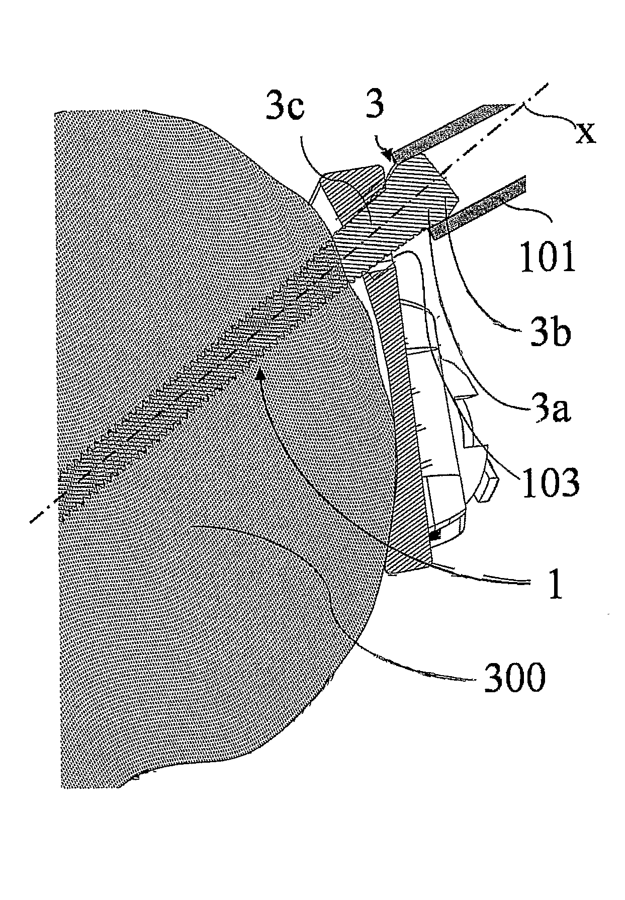
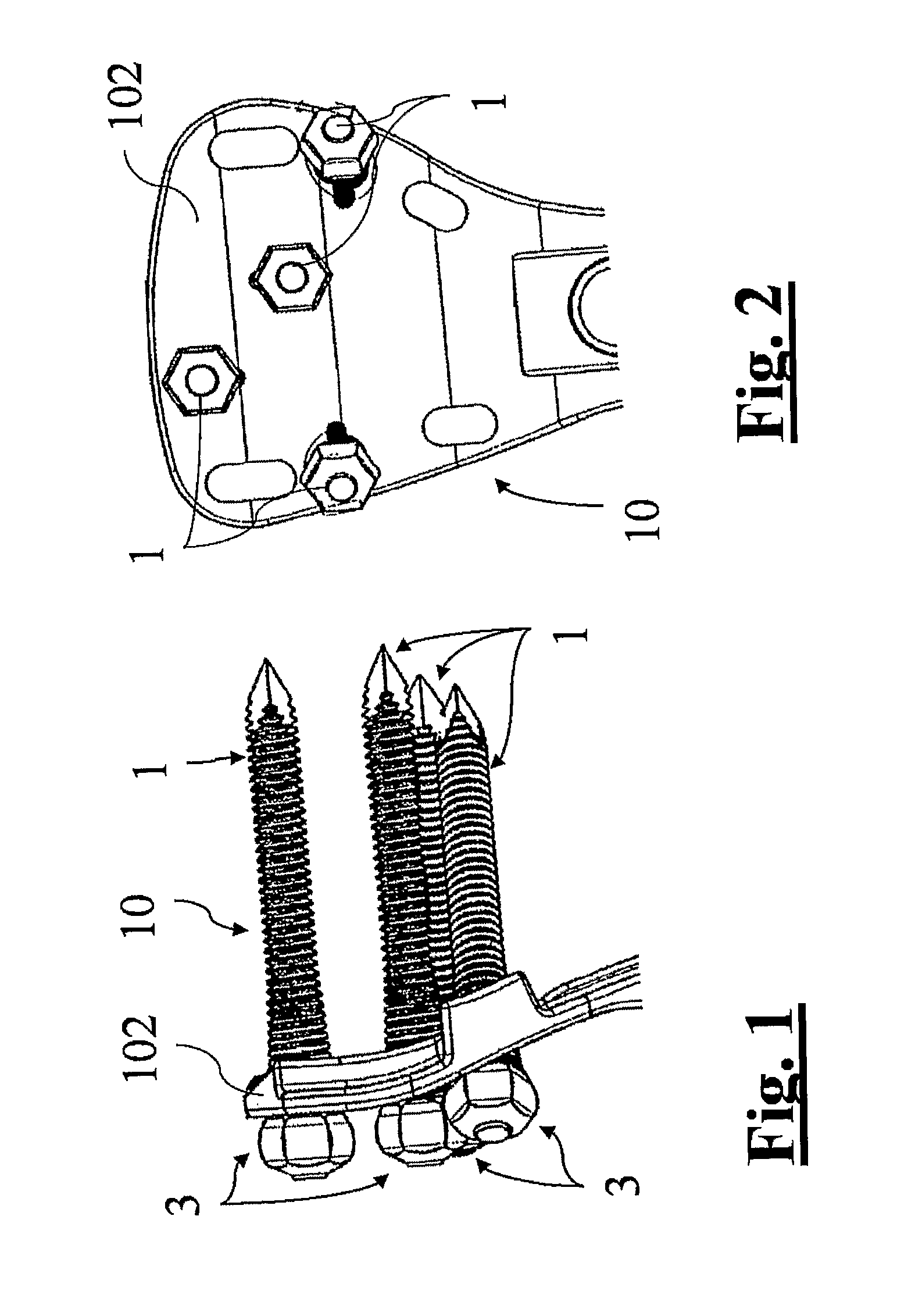
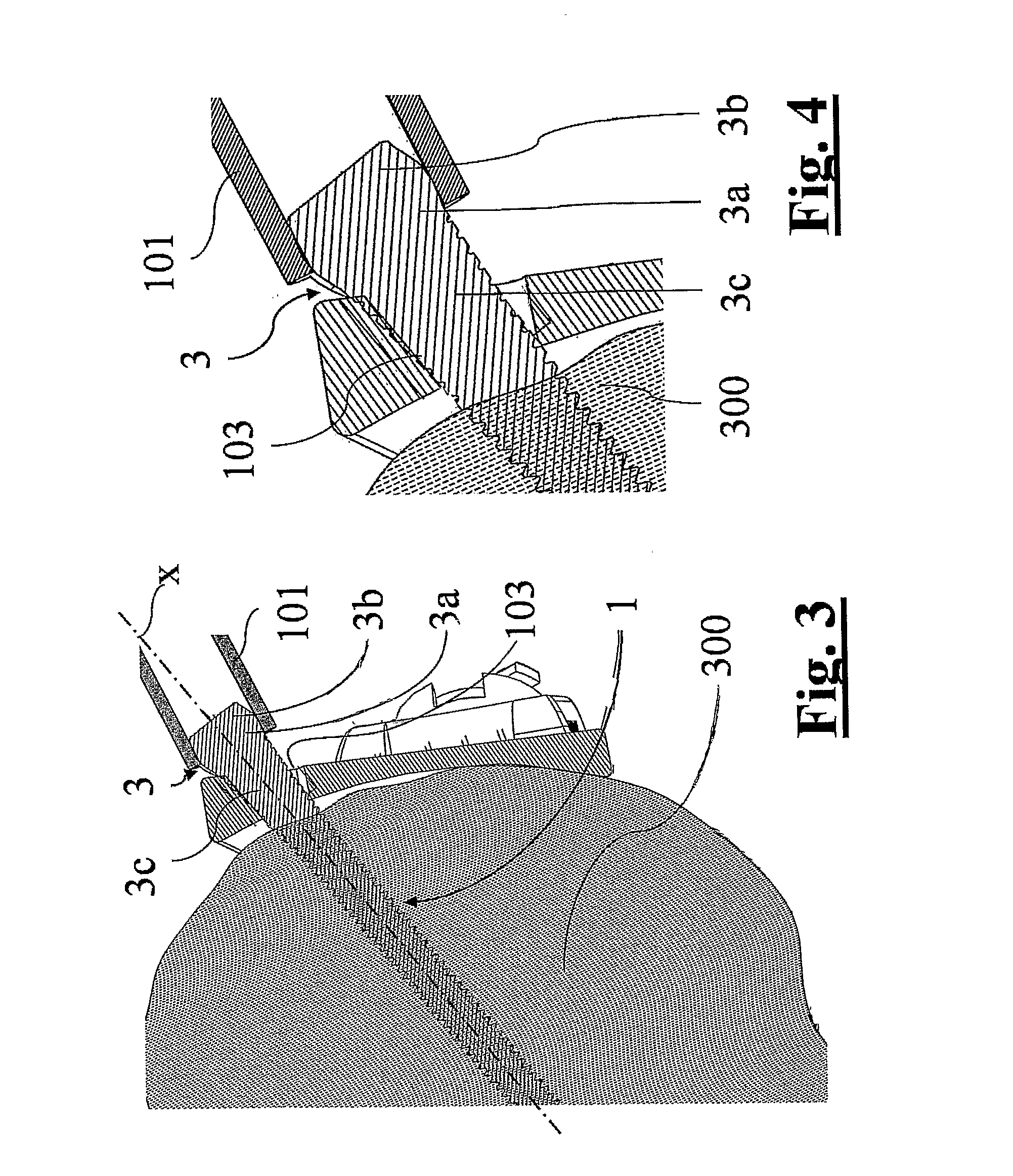
[0023]With reference to the appended figures, and in particular to FIGS. 1-4, the number of reference 10 generally indicates an orthopedic device for rigid osteosynthesis of fractures, of the type comprising a plate 102 with at least a through hole 103 and at least one endosseous screw 1 provided for insertion into said hole.

[0024]There is preferably more than one endosseous screw 1, four in the example shown in FIGS. 1 and 2.

[0025]The endosseous screw 1 according to the invention comprises a shaft 2, which is at least partially threaded, insertion means for inserting the screw into a bone site 300 and a distal portion of screw, which is provided for engaging the plate 102 in order to fasten the same to the bone site 300.

[0026]In particular, the distal portion 33 of the screw comprises a screw head 3 and a longitudinally extended portion.

[0027]The head 3 has facets 30 which define an external peripheral profile which may engage with a tubular manipulating wrench 101, to allow the sc...


PUM


Abstract

Endosseous screw (1) for fixing a plate (102) to a bone site (300), comprising an at least partially threaded shaft (2), insertion means for inserting the screw into a bone site and a distal portion (33) provided for engaging said plate to fasten it to said bone site and comprising a head (3) having facets (30) defining an external peripheral profile provided for engagement with a tubular manipulating wrench, to allow the screw (1) to be extracted from the bone site (300) into which it has been inserted, wherein the facets (30) are curvilinear and the external peripheral profile defined by same facets (30) has a convex barrel-like shape, in order to allow a stable coupling between the tubular manipulating wrench and said profile, which is maintained during the untightening phase of screw from plate, even when said tubular manipulating wrench is oriented in an inclined direction with respect to a longitudinal axis (x) of the endosseous screw (1).

Description

TECHNICAL FIELD[0001]The present invention refers to an orthopedic device for the osteosynthesis of fractures, of the type comprising a plate and endosseous screws for fixing the same to a bone site.[0002]The invention also refers to an endosseous screw for fixing a plate to a bone sitePRIOR ART[0003]In order to facilitate correct osteosynthesis of bone fractures following surgical reduction, it is a known practice to use orthopedic devices comprising plates fixed to the fractured site by means of a plurality of endosseous screws.[0004]Such screws, normally of the self-tapping and self-perforating type, may be adapted for engaging a support plate of the type called “with angular stability” by means of their cylindrical or conical threaded distal portion; this solution avoids angular micro-movements of the screw with respect to the plate, so that plate and engaged screws become a rigid, essentially monolithic body which is rigidly associated to the bone site.[0005]Endosseous screws, ...

Claims


Application Information

Patent Timeline
Patent Type & Authority Applications(United States)
IPC IPC(8): A61B17/86A61B17/80A61B17/56
CPCA61B17/8052A61B17/8605A61B2019/307A61B17/8635A61B17/8875A61B17/861A61B2090/037
Inventor VENTURINI, DANIELEMARAZZI, GIANCARLO
Owner ORTHOFIX SRL
Learn More