Reinforcement Bar Support Device

a technology of reinforcement bar and support device, which is applied in the direction of building reinforcements, building material handling, construction, etc., can solve the problems of high project cost, difficulty in achieving high project cost, and achieve the effect of full tensile strength capability, high project cost, and expensive and time-consuming corrections

Inactive Publication Date: 2011-10-13
HAMMON ADRIAN
View PDF32 Cites 9 Cited by
  • Summary
  • Abstract
  • Description
  • Claims
  • Application Information

AI Technical Summary

Benefits of technology

[0015]The primary purpose of the present invention is to provide means for positively placing and maintaining vertical and horizontal reinforcing bars at the precise positions in a concrete masonry wall. The present invention assures an engineer that reinforcement bar will remain at an intended location at all times, and its full tensile strength capability will be utilized. When installing a new wall, masons currently have to rely on thick concrete and good timing to ensure the reinforcement bar is held vertically inside the block wall or horizontally during the grouting process. This can be a difficult task, especially in high-lift grout applications. Mistakes during construction may necessitate expensive and time consuming corrections, which can result in higher project costs. If the individual or crew constructing the wall decides not to correct the positioning of the reinforcement bar, the integrity of the finished product may become compromised and potentially result in future structural problems. A device is needed that assists in the alignment and installation of reinforcement bar. The present invention fulfills this need.
[0016]The present invention maintains reinforcement bar placement by means of continuous, ladder-like assembly modules placed in the horizontal planar mortar joints of the wall at specified levels as the wall is built. The present invention is designed to locate the vertical and horizontal reinforcing bars at precise locations specified by the design. This wire device aids in the positioning of rebar in concrete m

Problems solved by technology

This can be a difficult task, especially in high-lift grout applications.
Mistakes during construction may necessitate expensive and time consuming corrections, which can result in higher project costs.
If the indivi

Method used


Image

  • Reinforcement Bar Support Device
  • Reinforcement Bar Support Device
  • Reinforcement Bar Support Device

Examples


Embodiment Construction

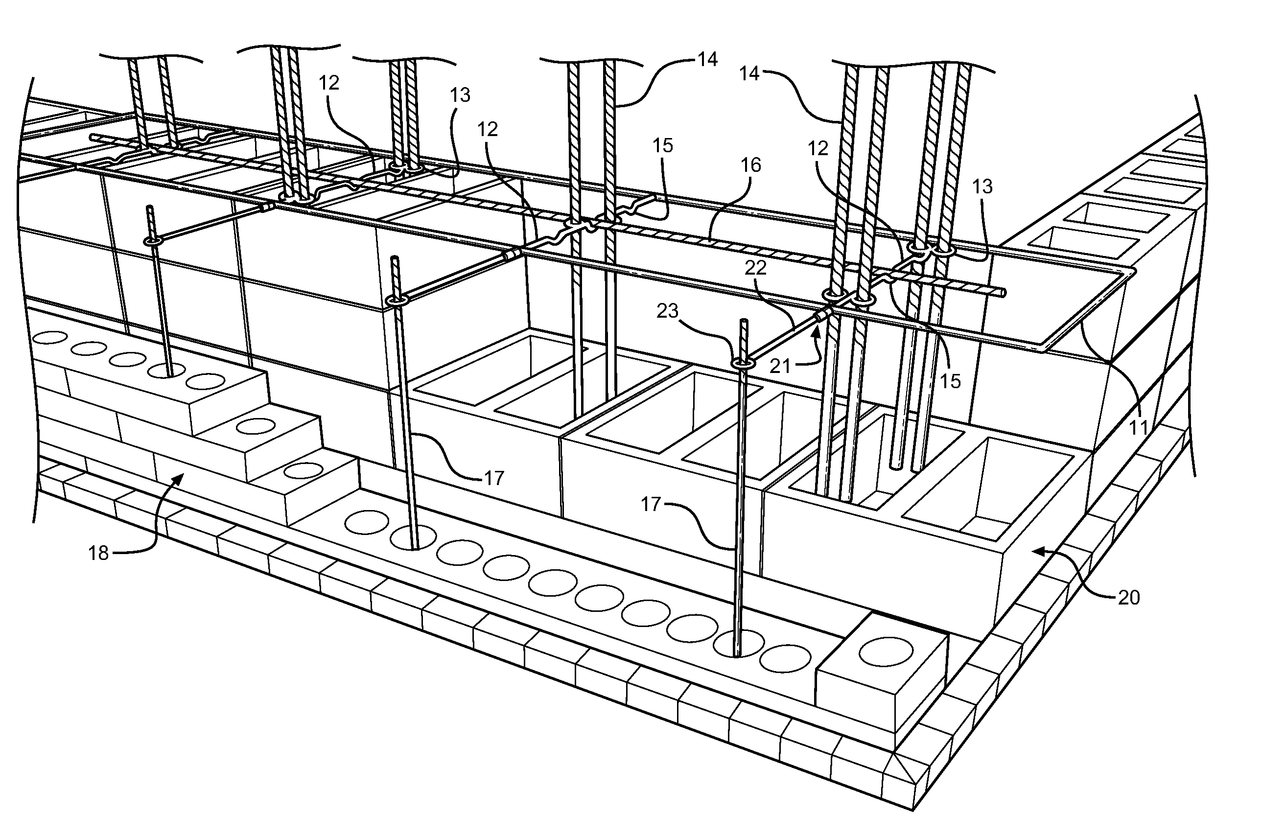
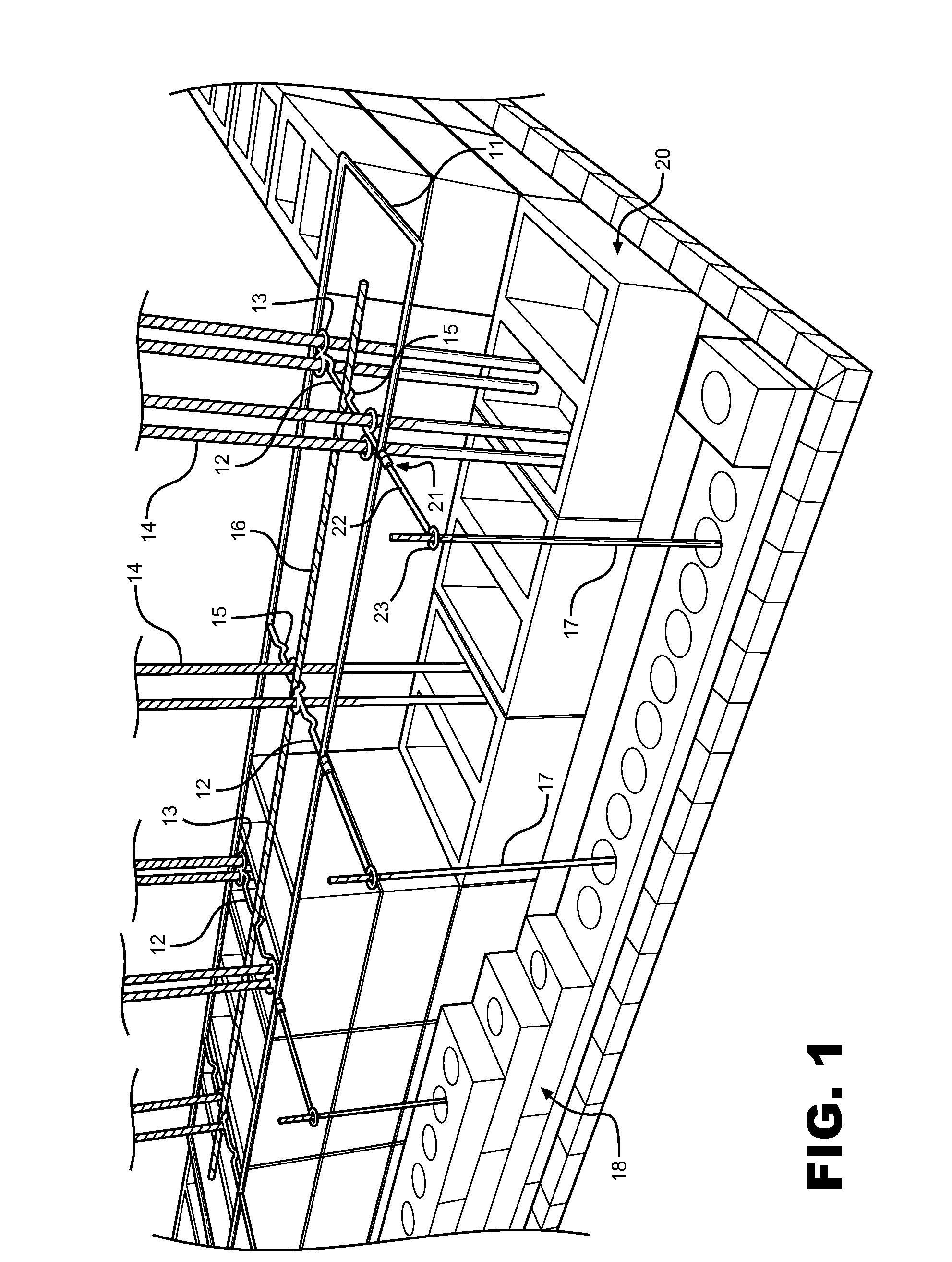
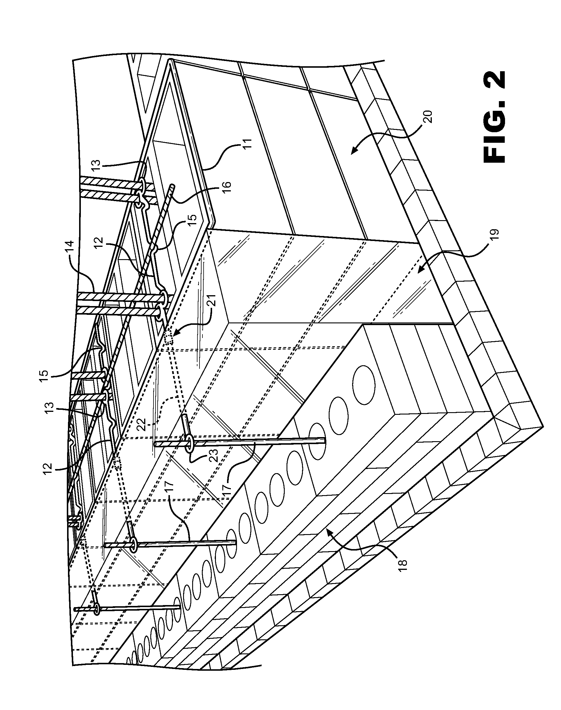
[0023]The present invention provides masons, construction crews, and other individuals with a modular reinforcement bar positioning system for use in concrete masonry unit walls. This device may be comprised of a modular, planar frame that holds a plurality of cross members, creating a design that is similar in appearance to a ladder. The gauge and material of the frame and cross members may be any suitable or desirable to one skilled in the art, include 9-gauge steel wire. Said cross members may be crimped for holding a horizontal rebar at precise locations or bent into circles for securing around a vertical reinforcement bar at a precise location. Each cross member may be spot welded at its ends to the frame. In use, the device may be placed along the length of the block wall in a horizontal mortar joint allowing individuals to securely place vertical and horizontal rebar in the correct positions within the blocks. Multiple modules of the device can be placed at varying levels to ...


PUM


Abstract

A modular wire device to support and maintain the position of horizontal and vertical reinforcement bars in concrete masonry unit walls. Additionally, the device may function to provide structural support and to act as the base for attaching insulation, bricks or other veneers to a wall structure. The wire support device comprises a planar wire frame to be set within horizontal mortar joints, coupled with a plurality wire cross members. The wire cross members may have crimps and loops to precisely align horizontal and vertical reinforcement bars. Hingedly attached extension members may extend outward from the wire frame and the face of the wall to vertical wire surface material supports using end loops to provide support for insulation, brick or other veneers. The frame and horizontal bars provide additional structural reinforcement across the wall thickness.

Description

CROSS REFERENCE TO RELATED APPLICATION[0001]This application claims the benefit of U.S. Provisional Application No. 61 / 321,518 filed on Apr. 7, 2010, entitled “Rebar Support.”FIELD OF THE INVENTION[0002]The present invention relates to a wire device to aid in the positioning of reinforcement bar in concrete masonry unit walls, while providing additional reinforcement through the thickness of the wall.DESCRIPTION OF THE PRIOR ART[0003]The present invention pertains to a modular wire reinforcement device used in concrete block construction. More particularly, the present invention is a device for the positioning of vertical and horizontal steel reinforcement bars precisely where intended. The present invention may also be used to support and provide attachment points for bricks, insulation and other veneers on the surface of the concrete masonry wall. Typical wall installations include an outer veneer of brick or other material, a middle layer of insulation, followed by a structural f...

Claims


Application Information

Patent Timeline
IPC IPC(8): E04C5/16E04B1/41E04B1/38
CPCE04B1/4185E04C5/166
Inventor HAMMON, ADRIAN
Owner HAMMON ADRIAN
Why Eureka
Try Eureka