Working table having vacuum mechanism

Inactive Publication Date: 2011-10-13
CHANG TJER INDAL
View PDF0 Cites 20 Cited by
  • Summary
  • Abstract
  • Description
  • Claims
  • Application Information

AI Technical Summary

Benefits of technology

[0011]The primary objective of the present invention is to provide a working table including a vacuum cleaner or vacuum mechanism for easily d

Problems solved by technology

However, no vacuum cleaners or vacuum mechanisms are provided for drawing and collecting the cut off dusts or contaminants such that the cut off dusts or contaminants may al

Method used


Image

  • Working table having vacuum mechanism
  • Working table having vacuum mechanism
  • Working table having vacuum mechanism

Examples


Embodiment Construction

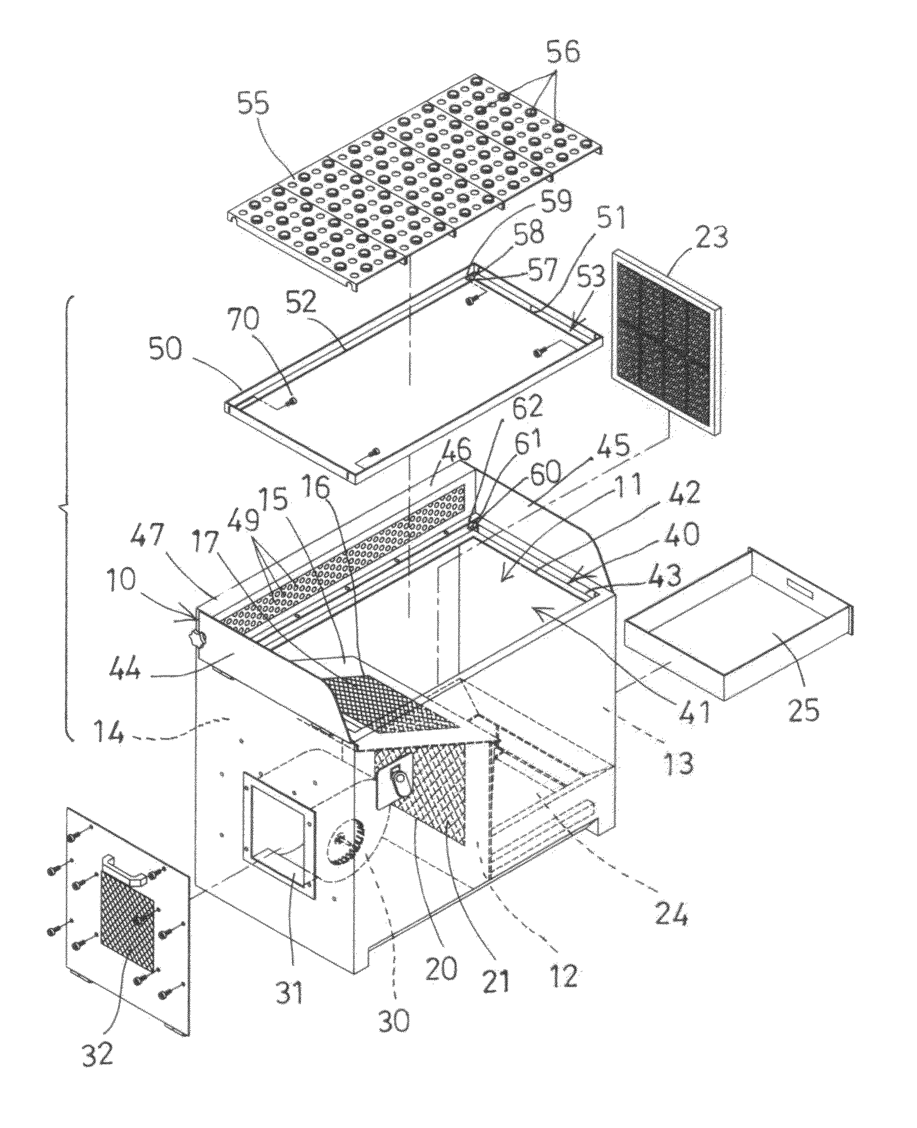
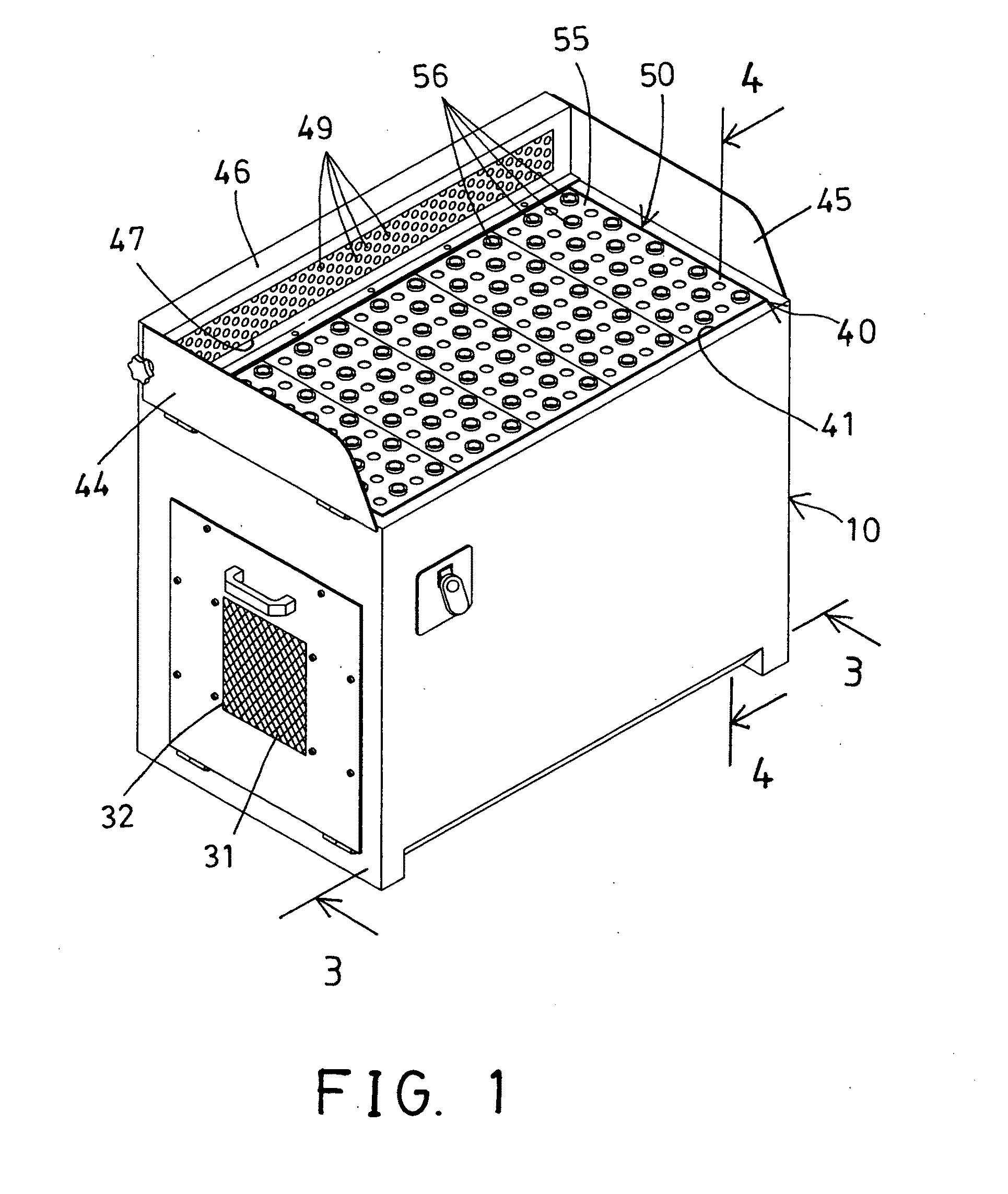
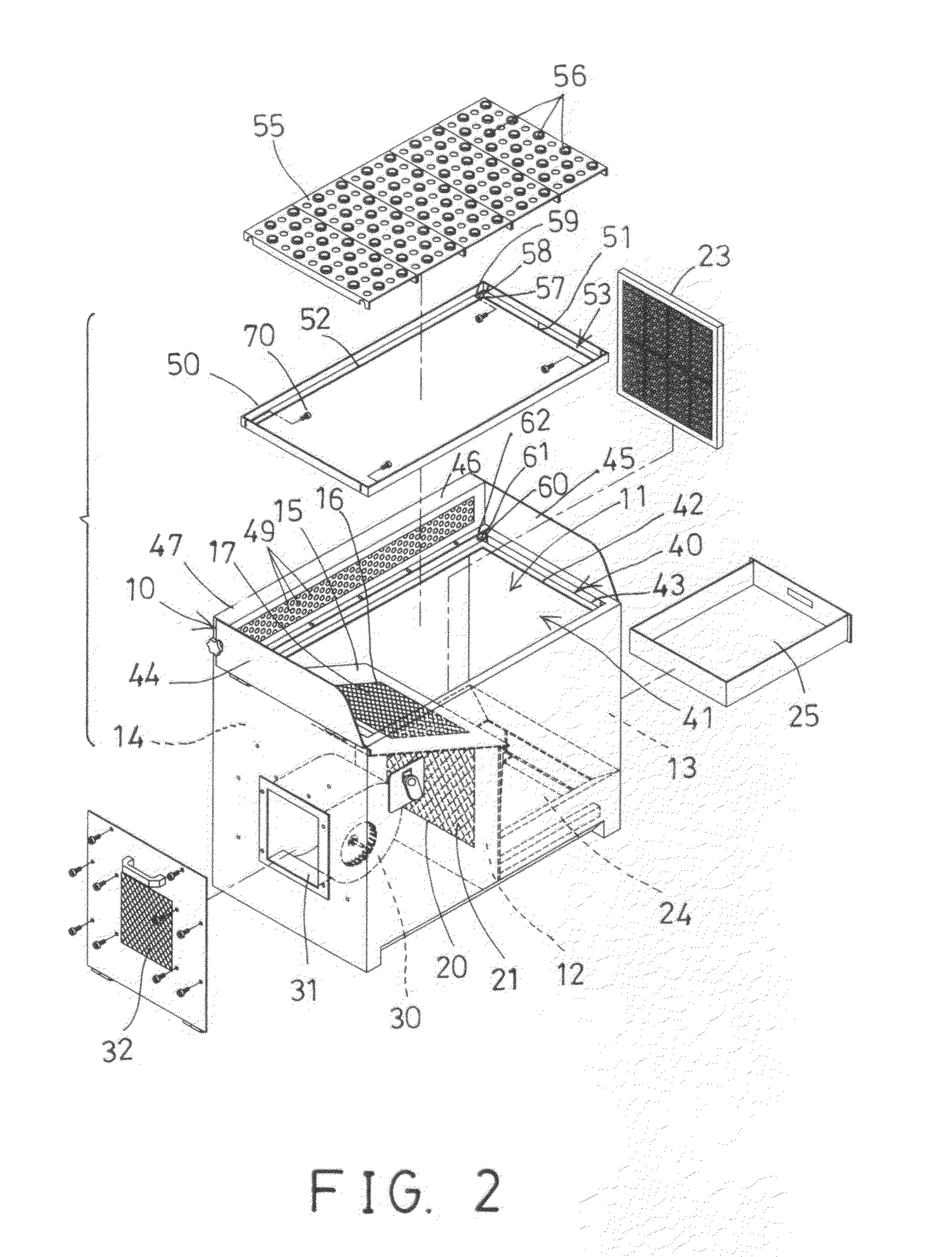
[0026]Referring to the drawings, and initially to FIGS. 1-3, a working table in accordance with the present invention comprises a receptacle or table housing 10 including a chamber 11 formed therein, and including a partition 12 disposed or attached or mounted or secured in the middle portion of the chamber 11 of the housing 10 for separating the chamber 11 of the housing 10 into a dust receiving and collecting compartment 13 and an air drawing and vacuuming compartment 14, and including a dust guide plate 15 disposed or attached or mounted in one side of the housing 10 and located above the air drawing and vacuuming compartment 14, and preferably tilted or inclined relative to the partition 12 and the housing 10 for suitably guiding and directing the dusts or contaminants into the dust receiving and collecting compartment 13 of the housing 10.

[0027]The dust guide plate 15 includes an opening 16 formed therein for attaching or mounting or securing a fine net member 17, and includes ...


PUM


Abstract

A working table including a partition separating a housing into a dust compartment and an air compartment, two side fences and a rear casing extended from a table top, the casing includes a chamber and a number of apertures communicative with the dust compartment of the housing, a filter member attached to the partition, a vacuuming device disposed in the air compartment of the housing, and a perforated platform adjustably attached to the table top and tiltable relative to the table top and the housing at a selected inclined angle for allowing the users to suitably work on top of the table top and the perforated platform without worrying the outwardly flying dusts and contaminants.

Description

BACKGROUND OF THE INVENTION[0001]1. Field of the Invention[0002]The present invention relates to a working table, and more particularly to a working table including a vacuum cleaner or vacuum mechanism for easily drawing and collecting the cut off dusts or contaminants and for allowing the collected dusts or contaminants to be easily removed or discarded.[0003]2. Description of the Prior Art[0004]Typical working tables, working machines, or table tools or table saws comprise a planar platform for supporting the work pieces, and a working tool for cutting or grinding or machining the work pieces.[0005]For example, U.S. Pat. No. 5,301,579 to Shiotani et al., and U.S. Pat. No. 6,532,643 to Wang disclose two of the typical table tools or scroll saw machines each also comprising a platform for supporting the work pieces, and a working tool for cutting or grinding or machining the work pieces, and a lot of cut off dusts or contaminants may be generated when the working tool is working on ...

Claims


Application Information

Patent Timeline
IPC IPC(8): A47B37/00
CPCB23Q11/0046B25H1/20B25H1/12B23Q11/0053
Inventor LIN, KUN YI
Owner CHANG TJER INDAL
Why Eureka
Try Eureka