Injectors utilizing lattice support structure

a technology of support structure and injector, which is applied in the direction of machines/engines, lighting and heating apparatus, applications, etc., can solve the problems of limiting the geometry of typical parts, limiting the size of state of the art devices produced from cast, forged or wrought products, and difficult machineability of superalloys typically used for withstanding such conditions

Inactive Publication Date: 2011-10-13
DELAVAN
View PDF9 Cites 59 Cited by
  • Summary
  • Abstract
  • Description
  • Claims
  • Application Information

AI Technical Summary

Benefits of technology

[0009]The subject invention is directed to a new and useful fuel injector for a gas turbine engine. The fuel injector includes an inlet having a fuel inlet fitting for receiving fuel. A feed arm is mounted to the inlet and has an internal conduit in fluid communication with the inlet for conveying fuel from the inlet fitting through the feed arm. A nozzle body is operatively connected to the feed arm for injecting fuel from the internal conduit into a combustor of a gas turbine engine. At least one of the inlet, feed arm, and nozzle body includes a lattice support structure.

Problems solved by technology

Superalloys typically used for withstanding such conditions are difficult to machine.
The state of the art devices produced from cast, forged, or wrought products are generally limited to shapes and sizes that can be machined or generated through traditional subtractive manufacturing methods.
The limitations involved in subtractive machining generally leave more material in a given component than is actually necessary to supply the requisite strength or material properties.
As a result, typical parts are geometry-limited and are substantially heavier than desired.
But due to the limitations of the subtractive machining processes, some material is left behind that is not needed, structurally or otherwise, simply because the material cannot be reached for removal by conventional processes without removing other structures that are necessary.
Known parts utilizing cast trusses, wire pads, metallic foams, and the like for weight reduction suffer substantially from randomness in the structures and related analytical difficulties, and / or size and geometry limitations as in cast components.

Method used


Image

  • Injectors utilizing lattice support structure
  • Injectors utilizing lattice support structure
  • Injectors utilizing lattice support structure

Examples


Embodiment Construction

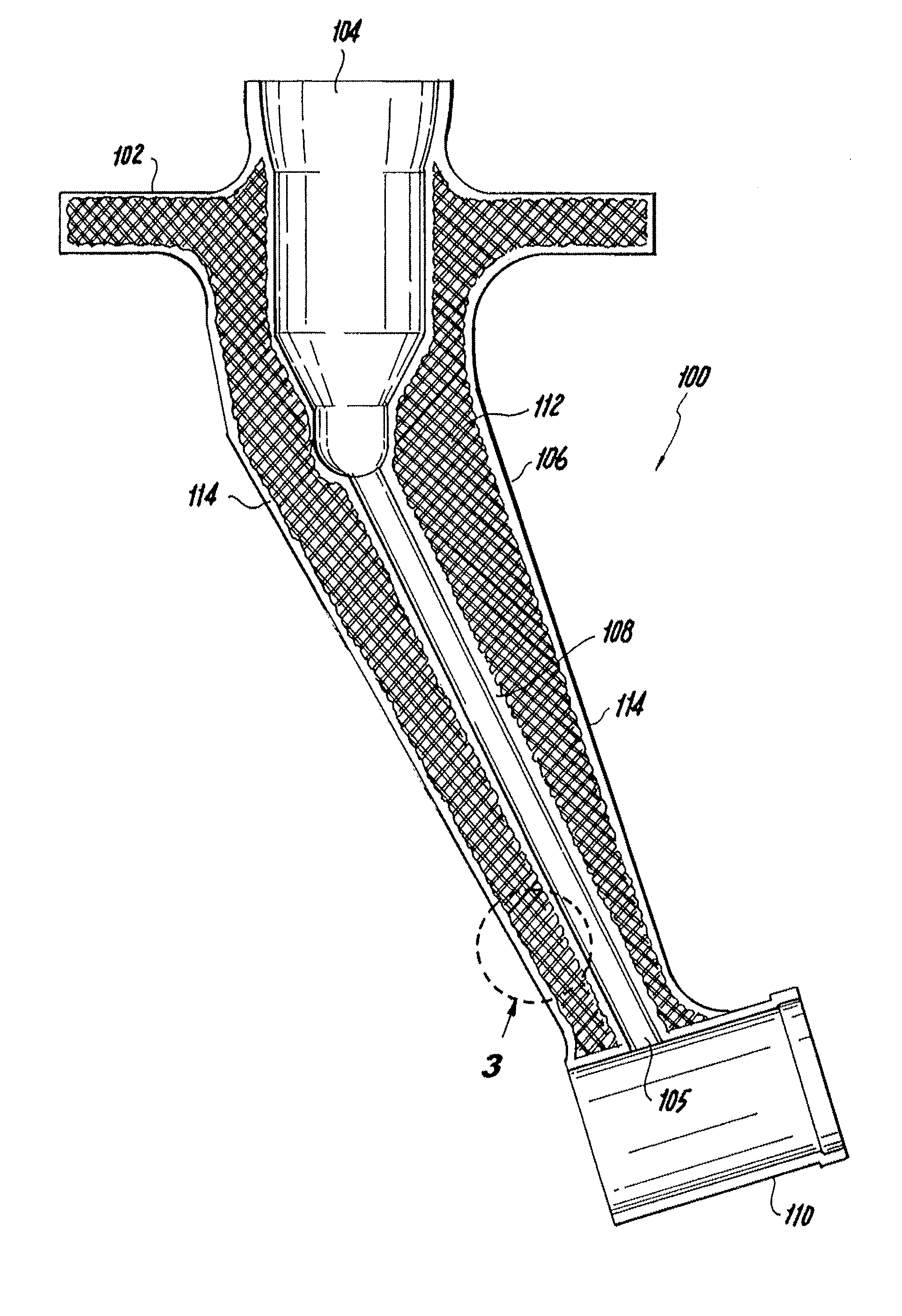
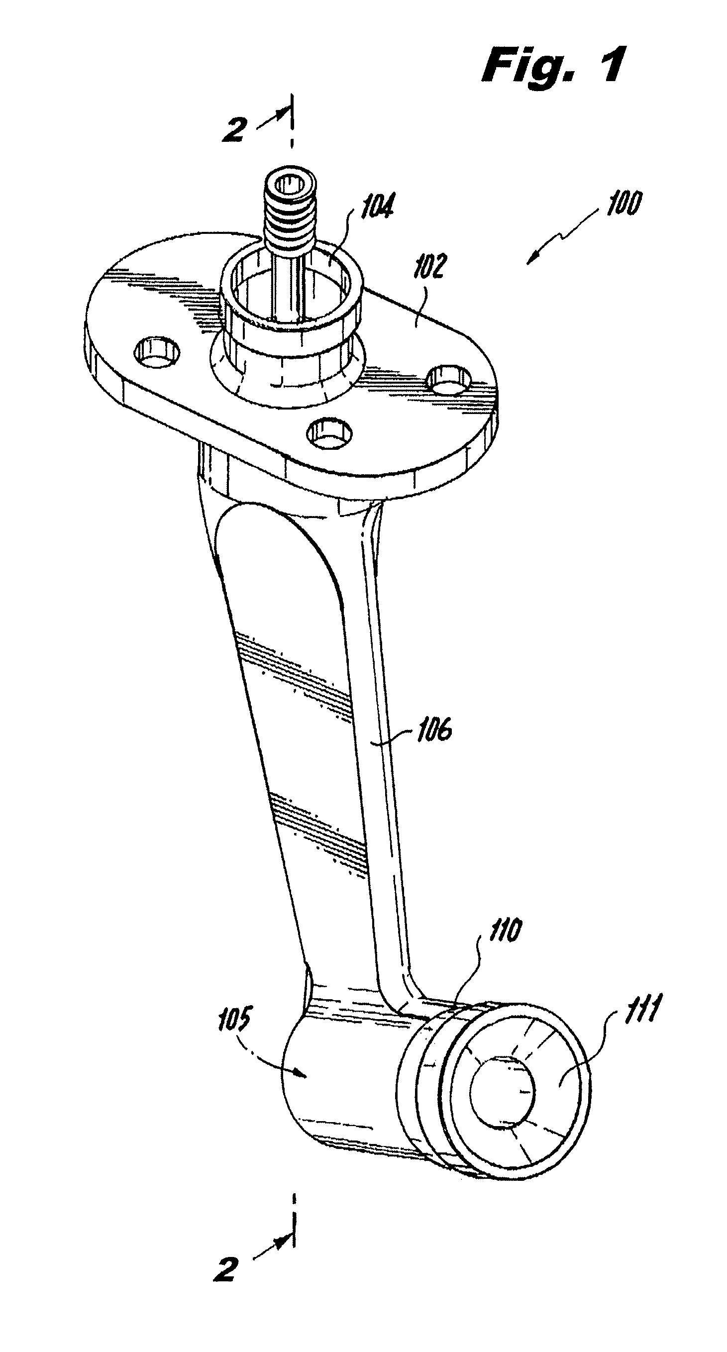
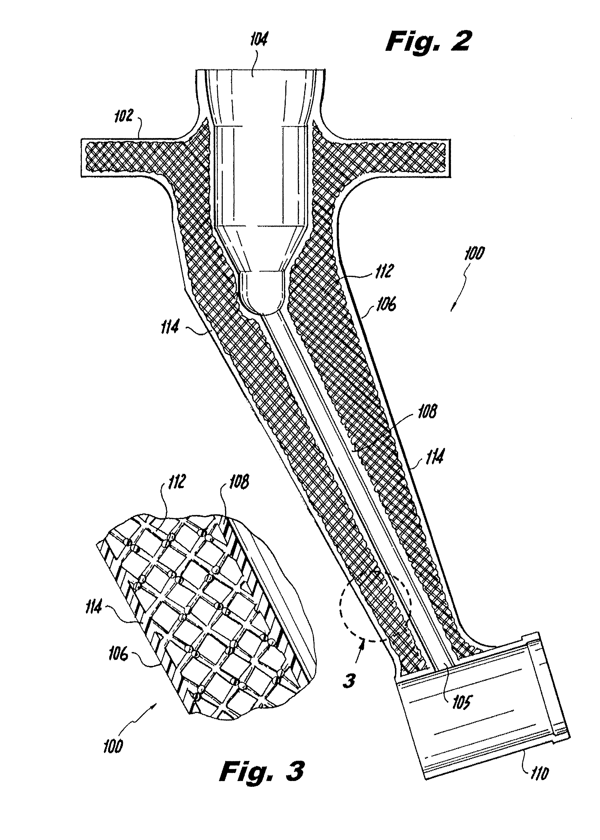
[0030]Reference will now be made to the drawings wherein like reference numerals identify similar structural features or aspects of the subject invention. For purposes of explanation and illustration, and not limitation, a partial view of an exemplary embodiment of a fuel injector in accordance with the invention is shown in FIG. 1 and is designated generally by reference character 100. Other embodiments of fuel injectors in accordance with the invention, or aspects thereof, are provided in FIGS. 2-12, as will be described. The methods and systems of the invention can be used to increase structural intricacy and to reduce weight in injectors and injector components.

[0031]Referring now to FIG. 1, fuel injector 100 for a gas turbine engine is shown, including a mounting flange 102 having a fuel inlet 104 with an inlet fitting for receiving fuel. A feed arm 106 is mounted to mounting flange 102 and has an internal conduit 108 (see FIG. 2) in fluid communication with fuel inlet 104 for ...


PUM

PropertyMeasurementUnit
weightaaaaaaaaaa
volumeaaaaaaaaaa
weightaaaaaaaaaa

Abstract

A fuel injector for a gas turbine engine includes an inlet having a fuel inlet fitting for receiving fuel. A feed arm is mounted to the inlet and has an internal conduit in fluid communication with the inlet for conveying fuel from the inlet fitting through the feed arm. A nozzle body is operatively connected to the feed arm for injecting fuel from the internal conduit into a combustor of a gas turbine engine. At least one of the inlet, feed arm, and nozzle body includes a lattice support structure.

Description

BACKGROUND OF THE INVENTION[0001]1. Field of the Invention[0002]The present invention relates to injectors and atomizers, and more particularly to support structures of injectors and atomizers for gas turbine engines.[0003]2. Description of Related Art[0004]A variety of devices are known in the art for injection and atomization of liquids. One exemplary application for such devices is in fuel injection for gas turbine engines. Typical fuel injectors include an inlet fitting where fuel is introduced into the injector from a fuel line or manifold. Many fuel injectors include a feed arm structure extending from the inlet fitting to a nozzle body, where fuel is issued from the injector into a combustor, typically as an atomized spray.[0005]Known injector designs typically rely on some form of metallic conduit or tube to deliver fuel from a supply manifold to a nozzle body or atomizing tip. For strength, thermal management, and aerodynamic purposes, fuel tubes are typically brazed or wel...

Claims


Application Information

Patent Timeline
Patent Type & Authority Applications(United States)
IPC IPC(8): F02M61/14B23P15/00
CPCY10T29/49432F23R3/283
Inventor DONOVAN, MATTHEW RAYMOND
Owner DELAVAN
Why Eureka
Try Eureka