Image display apparatus and image displaying method

Inactive Publication Date: 2011-10-13
SONY CORP
View PDF4 Cites 16 Cited by
  • Summary
  • Abstract
  • Description
  • Claims
  • Application Information

AI Technical Summary

Benefits of technology

[0015]Therefore, in the technique disclosed in Japanese Unexamined Patent Application Publication No. 2007-240798, luminance deterioration caused due to the deterioration in the light-emitting element is prevented in an image displayed on the display panel by detecting the deterioration in the light-emitting luminance on the entire screen using dummy pixels and correcting a driving signal of the panel by the detected deterioration in the light-emitting luminance.
[0024]In light of the foregoing, it is desirable to provide a technique for satisfactorily correcting deterioration in an image display panel with pixels including a self luminous element even when images with various raster sizes are displayed.

Problems solved by technology

Therefore, when the light-emitting elements display images for a long time, this problem may arise due to the fact that the light-emission luminance of each pixel deteriorates.
Since deterioration characteristics of the light-emission luminance of each pixel are different for each primary color, the deterioration in the light-emission luminance results in changing chromaticity.
Therefore, portions with strong luminance and portions with weak luminance occur within one display screen, thereby causing an undesirable result.
In the actual image display apparatus, it is difficult to determine a history of how long an image with a certain raster size is displayed.
Moreover, in the related art, correction of the light emission luminance of the pixels is not performed in consideration of the non-display portion occurring due to the difference in the raster size.

Method used


Image

  • Image display apparatus and image displaying method
  • Image display apparatus and image displaying method
  • Image display apparatus and image displaying method

Examples


Embodiment Construction

[0042]Embodiments of the invention will be described in the following sequence.

[0043]1. Overview of Color Temperature Correction according to Embodiment (FIGS. 1A to 3H)

[0044]2. Configuration of Apparatus according to Embodiment (FIGS. 4 and 5)

[0045]3. Exemplary Setting of Area division and Dummy Pixel according to Embodiment (FIGS. 6 and 7)

[0046]4. Exemplary Correction Processing according to Embodiment (FIGS. 8A to 8C)

[0047]5. Exemplary Processing of Joint Area according to Embodiment (FIGS. 9A to 11)

[0048]6. Modified Examples

1. Overview of Color Temperature Correction According to Embodiment

[0049]First, the overview of color temperature correction according to an embodiment will be described with reference to FIGS. 1A to 3H.

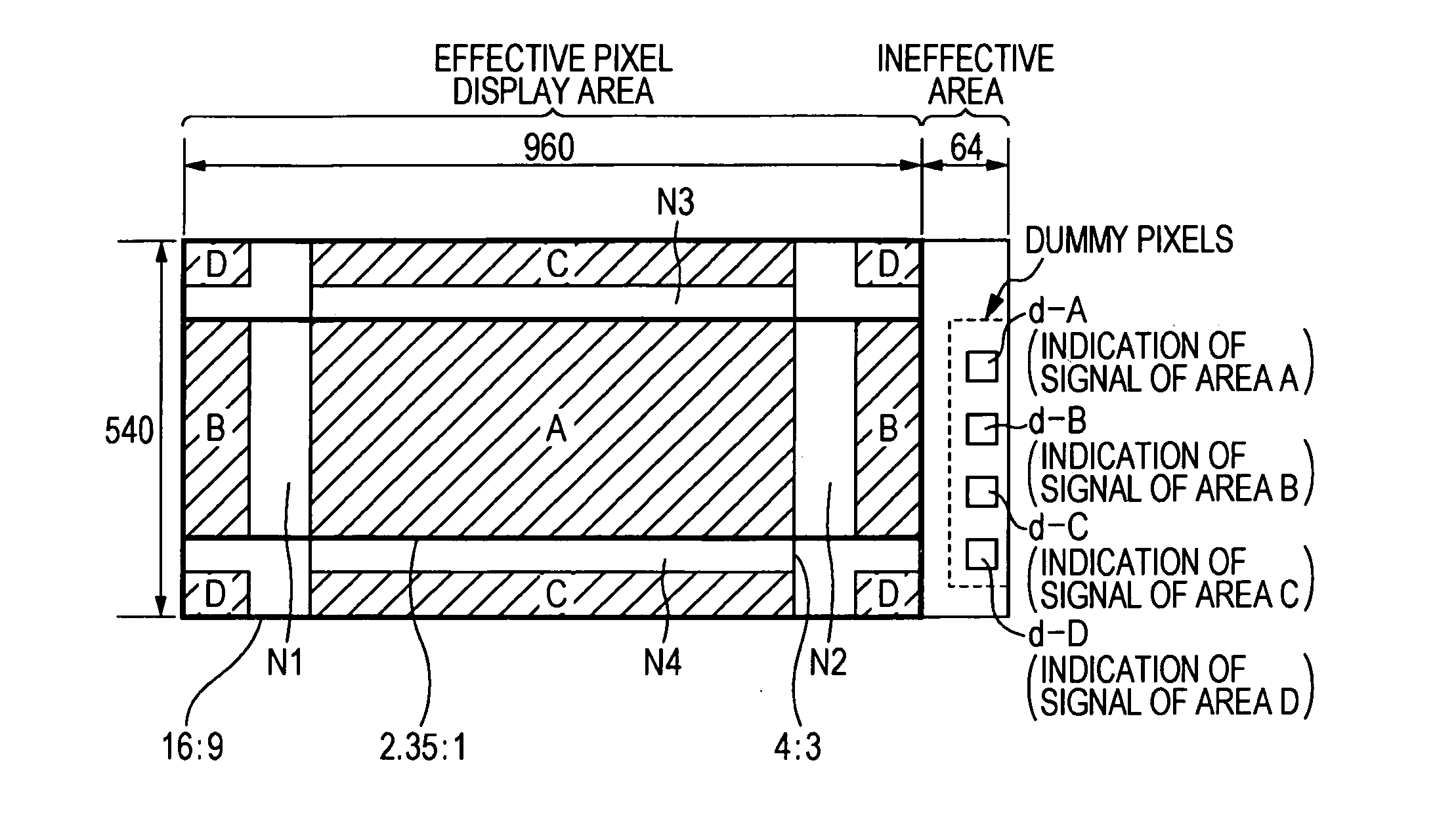
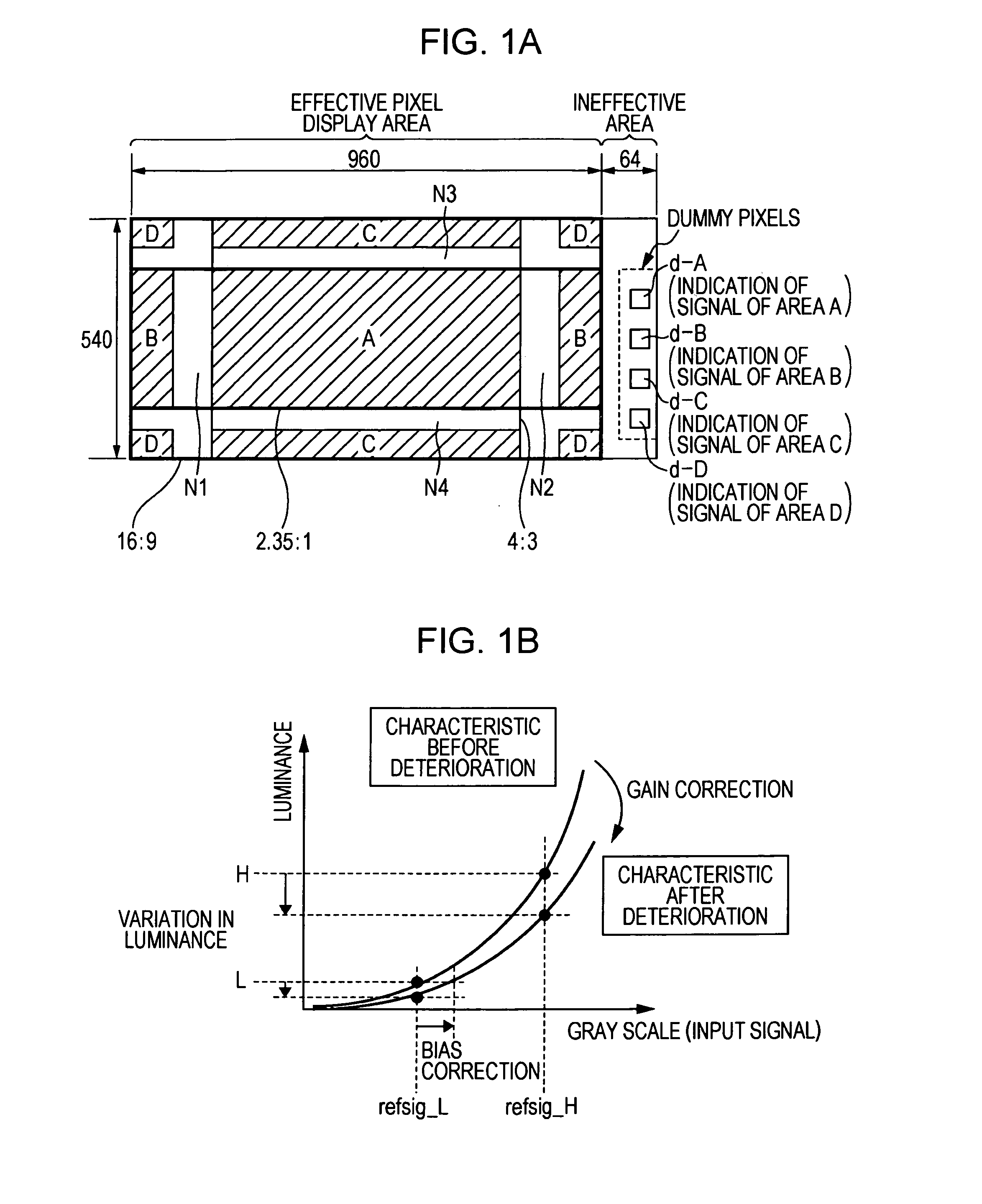
[0050]In the embodiment, an organic EL panel in which pixels, each include a self luminous element is used as an image display panel of an image display apparatus.

[0051]The image display panel has 540 pixels in a vertical direction and 960 pixels in a horizont...


PUM


Abstract

An image display apparatus includes: a display panel including an image display area and a dummy pixel area different from the image display area; an optical sensor detecting light emission luminance of the dummy pixel area on the display panel; and a control unit dividing the image display area on the display panel into a plurality of division areas, allowing pixels within the dummy pixel area to perform light emission to the same degree as the light emission of one or a plurality of pixels within each division area, and correcting luminance or chromaticity of the pixels within each division area based on the light emission luminance of the dummy pixel area detected by the optical sensor.

Description

CROSS-REFERENCE TO RELATED APPLICATION[0001]The present application claims priority from Japanese Patent Application No. JP 2010-090815 filed in the Japanese Patent Office on Apr. 9, 2010, the entire content of which is incorporated herein by reference.BACKGROUND OF THE INVENTION[0002]1. Field of the Invention[0003]The present invention relates to an image display apparatus and an image display method using a self-luminous display panel such as an organic EL (Electro-Luminescence) panel, and more particularly, to a technique for correcting deterioration in light-emission luminance.[0004]2. Description of the Related Art[0005]There have been developed various kinds of display apparatuses displaying an image through self emission of pixels arranged in a matrix form on a display panel. For example, display apparatuses using an organic EL panel have been put into practical use. The organic EL panel is an image display device that has high light-emission luminance of pixels and is excell...

Claims


Application Information

Patent Timeline
IPC IPC(8): G09G5/10G06F3/038
CPCG09G3/3225G09G2300/0413G09G2320/029G09G2320/0693G09G2320/0666G09G2320/0686G09G2320/043
Inventor TAKUMA, HIROKAZU
Owner SONY CORP
Why Eureka
Try Eureka