Display device, display device driving method and source driving circuit

a display device and driving circuit technology, applied in the field of display technology, can solve the problems of increasing power consumption and achieve the effect of improving power saving

Active Publication Date: 2011-10-13
AU OPTRONICS CORP
View PDF13 Cites 32 Cited by
  • Summary
  • Abstract
  • Description
  • Claims
  • Application Information

AI Technical Summary

Benefits of technology

[0007]Accordingly, the present invention is directed to a display device, can use a charge sharing operation to achieve the purpose of save power.
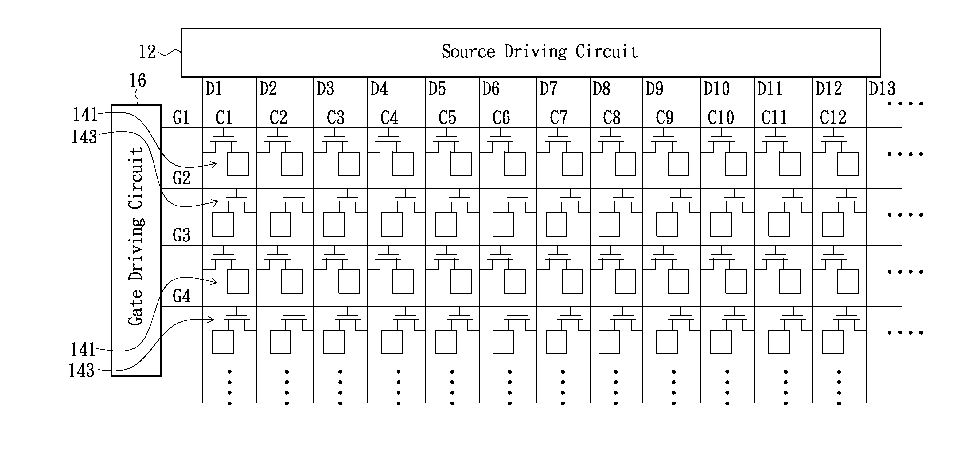
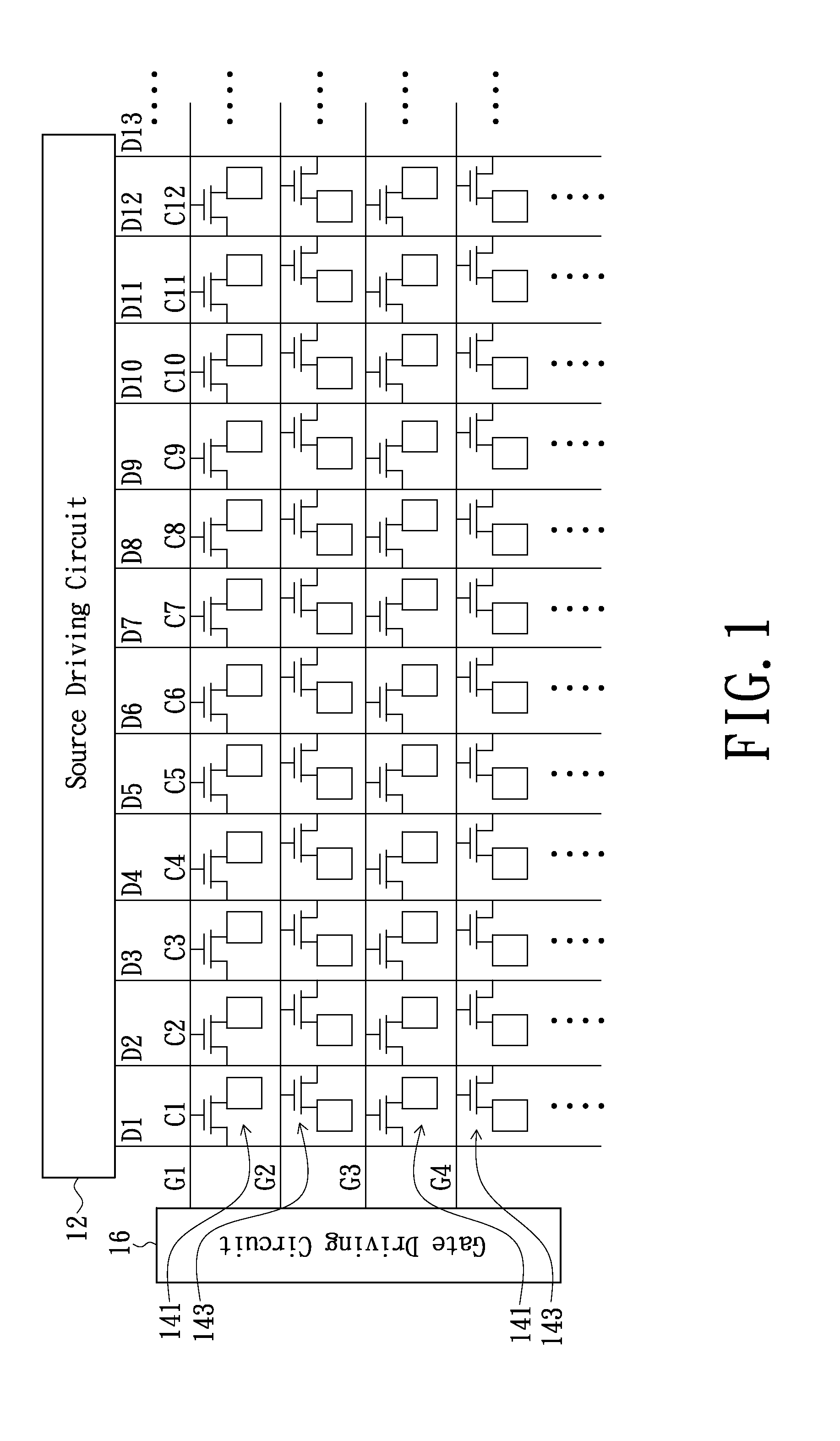
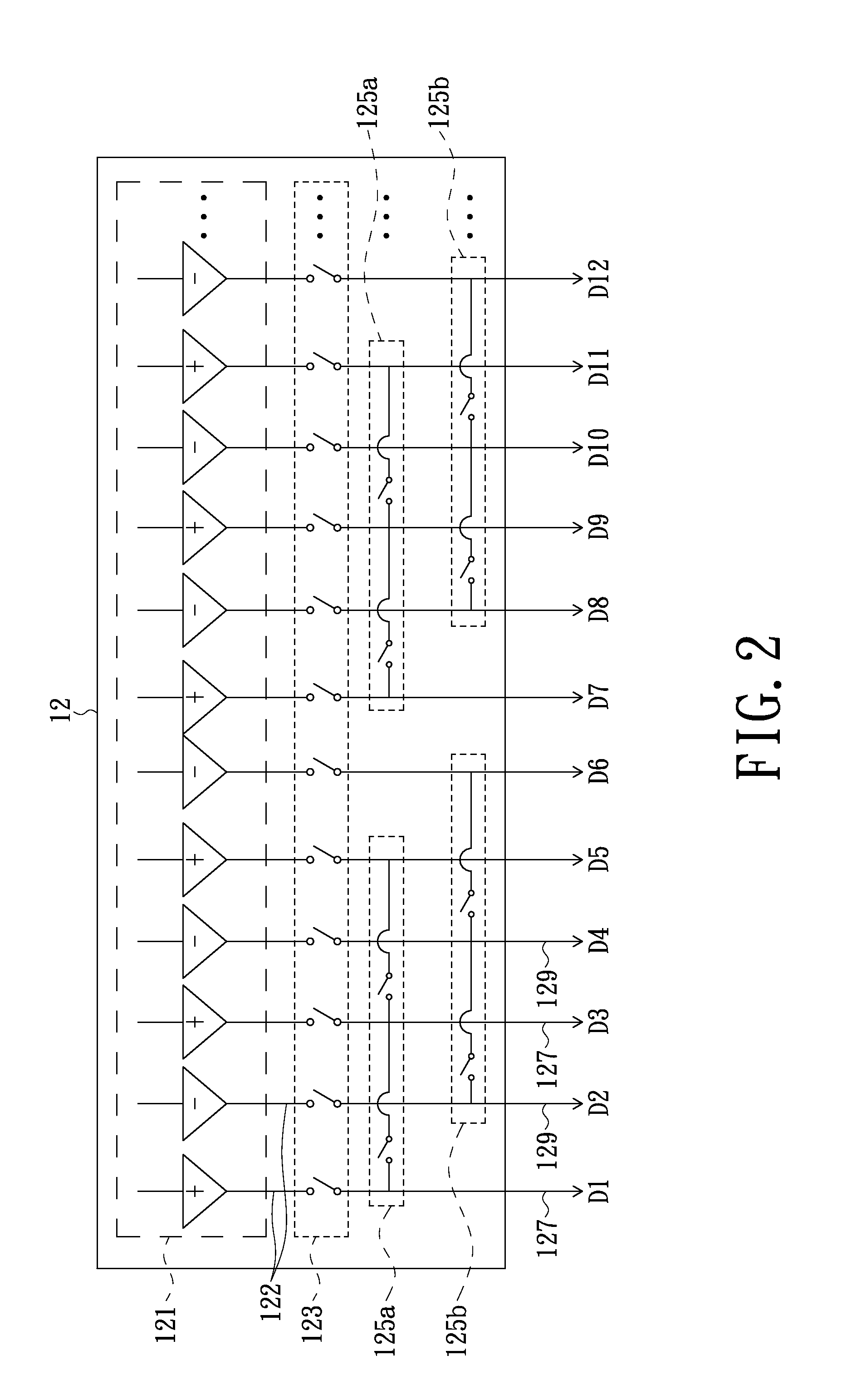
[0021]In summary, the above-mentioned embodiments of the present invention employ at least one first charge sharing switch circuit and at least one second charge sharing switch circuit, which facilitates multiple data lines provided with display data having same polarity to mutually share charges, while data lines provided with display data having different polarities mutually are not performed with charge sharing. Accordingly, it is feasible for the display device adopting both zigzag pixel arrangement and column inversion driving type to perform the charge sharing operation and thereby achieving better power saving effect.

Problems solved by technology

In another aspect, the prior art has proposed a solution of charge sharing (i.e., data lines respectively given positive and negative polarities are connected together to mutually share charges before polarities are inversed), and about 50% dynamic power theoretically can be saved; however, it is unfeasible to make the data lines with the respective positive and negative polarities to share charges in the liquid crystal display device adopting both the zigzag pixel arrangement and column inversion driving type, or else, much more power consumption is caused.

Method used


Image

  • Display device, display device driving method and source driving circuit
  • Display device, display device driving method and source driving circuit
  • Display device, display device driving method and source driving circuit

Examples


Embodiment Construction

[0028]In the following detailed description of the preferred embodiments, reference is made to the accompanying drawings which form a part hereof, and in which are shown by way of illustration specific embodiments in which the invention may be practiced. In this regard, directional terminology, such as “row,”“column,” etc., is used with reference to the orientation of the Figure(s) being described. The components of the present invention can be positioned in a number of different orientations. As such, the directional terminology is used for purposes of illustration and is in no way limiting. On the other hand, the drawings are only schematic and the sizes of components may be exaggerated for clarity. It is to be understood that other embodiments may be utilized and structural changes may be made without departing from the scope of the present invention. Also, it is to be understood that the phraseology and terminology used herein are for the purpose of description and should not be...


PUM


Abstract

A display device includes multiple first data lines, multiple second data lines, multiple pixel columns, at least a first charge sharing switch circuit and at least a second charge sharing switch circuit. The second data lines are alternately arranged with the first data lines. Each of the pixel columns includes multiple first pixels and multiple second pixels. The first pixels of each of the pixel columns are coupled to one of the first data lines, and the second pixels of each of the pixel columns are coupled to one of the second data lines. The first charge sharing switch circuit each is electrically coupled to at least a part of the first data lines. The second charge sharing switch circuit each is electrically coupled to at least a part of the second data lines. A display device driving method and a source driving circuit also are provided.

Description

BACKGROUND[0001]1. Technical Field[0002]The present invention generally relates to display technology fields and, particularly to a display device structure, a display device driving method and a source driving circuit structure.[0003]2. Description of the Related Art[0004]Nowadays, liquid crystal display devices have many advantages of high display quality, small volume, lightweight and wide application range and thus are widely used in consumer electronics products such as mobile phones, laptop computers, desktop computers and televisions, etc. Moreover, the liquid crystal display devices have evolved into a mainstream display device in place of cathode ray tube (CRT) display devices.[0005]In regard to the liquid crystal display device, since the property of liquid crystal materials polarities of voltages applied on a liquid crystal cell of pixel are needed to be alternately switched, and the process of the polarities of voltages applied on the liquid crystal cell being switched a...

Claims


Application Information

Patent Timeline
Patent Type & Authority Applications(United States)
IPC IPC(8): G06F3/038G09G3/36
CPCG09G3/3614G09G2330/021G09G2300/0426
Inventor LIN, YI-FANTUNG, MU-LINHSU, CHAO-CHING
Owner AU OPTRONICS CORP
Why Eureka
Try Eureka