
Quick-Release ATV Skis

Active Publication Date: 2011-10-20
RIVARD GREGORY A
View PDF11 Cites 19 Cited by
  • Summary
  • Abstract
  • Description
  • Claims
  • Application Information

AI Technical Summary

Benefits of technology

[0019]In a first manifestation, the invention is a quick-release ATV ski. A ski-shaped wheel support holds a pair of wheel receivers longitudinally along the support and spaced laterally from each other to define a wheel cage. A strap anchor is adjacent a first end of the wheel cage. An over-center clamp is adjacent a second end of the wheel cage distal to the first end. A strap is coupled between strap anchor and over-center clamp. A removable lock positively engages the over-center clamp and thereby prevents accidental release of the over-center clamp.
[0023]A first object of the invention is to enable a wheeled or track motor vehicle to be converted to a runner vehicle for operation in more extreme conditions than would be achieved with the wheels and at less load upon the motor and transmission than would be achieved with the tracks. A second object of the invention is for this conversion be intuitive, require minimal time and effort, and most preferably, not require tools or jacking of the vehicle. An additional object of the invention is to be compatible with tires of diverse width and diameter. Another object of the present invention is to ensure that, when properly installed and used, the runners will operate in a safe manner and will not harm the vehicle or operator. A further object of the invention is to enable an ATV front wheel set to be fit with runners, to reduce the load on the motor and transmission in heavy snow or deep mud. Yet another object of the present invention is to allow an ATV to be fit with rear tracks and front skis, or to be fit with four tracks and to convert the front two tracks into runners.

Problems solved by technology

In spite of the many benefits derived from an ATV, they do have limitations.
While an ATV can pass through relatively shallower snow depths, as the snow deepens, the ATV will sink into the snow, and passage through the snow becomes sufficiently difficult that the ATV motor and transmission may be damaged.
Furthermore, tracks require more power to drive and operate, regardless of the surface, than tires that are operated on relatively smooth and level ground.
Consequently, even in the case of an all-wheel drive ATV, the tracks require enough more power that an operator may accidentally overwork the engine and transmission.
They also have the unfortunate limitation of disabling, and in most cases, completely removing the drive wheels.
This leaves the vehicle disabled except when there is sufficient snow, mud or other slippery surface for the runners to slide.
Furthermore, an operator must spend a substantial amount of time removing each tire and replacing it, time that further includes undesirable risks associated therewith.
These risks include potential damage to the tires, hubs, or the person doing the work.
As a result, only the most critical of applications will lead an owner or operator to carry out the work of switching away from tires, and, then once switched, the owner or operator will be quite reluctant to switch back.
This technology allows the operator to leave wheels attached to hubs, but is not without other limitations.
There are several limitations that carry throughout most of the prior art.
One limitation is the undesirable need to lift or jack the vehicle wheels up in order to install the skis As might be appreciated, jacking or otherwise lifting a vehicle always presents undesirable risk, requires significant time, and limits when and where the runners may be attached.
Another prior art limitation is the need to secure directly to a portion of the wheel inside of the outer circumference.
This can lead to unintended damage or deformation of the rim.
Yet another prevalent limitation is the need for tools to execute the attachment and removal of the runners.
Unfortunately, and depending upon the vehicle, travel speed, and surface being traversed, very large twisting forces or torque may be applied between the runner and tire.
The lack of additional structure enables undesirable movement between runner and tire, and can lead to dangerous separation therebetween.
However, the pocket has low wall height, in all likelihood to facilitate drive-on capability, but this low wall height also means that there is almost no effective wall support, meaning that this design is prone to limitations similar to Stryker and Bryant et al above, where the lack of sufficient additional wall structure enables undesirable twisting movement between runner and tire, and can lead to dangerous separation therebetween.
In other words, if the walls of Chase are elevated, then the vehicle will need to be lifted in, but if the walls are lower to permit drive-in coupling, then there will not be sufficient support to prevent relative twisting between tire and runner.
This limits that concept to a particular wheel type and diameter, and, since the securement tends to be localized to the single fastener passing inside of the tire rim, in the event large forces are applied to the ski or runner, the forces will not be evenly distributed throughout the tire, and instead will be concentrated at the single anchor point.
This can lead to unintended damage or deformation of the rim.
The Cartwright patent overcomes many of the aforementioned limitations, but does not clearly permit drive-on installation, and definitely requires the use of tools to enable the apparatus to be attached to a tire.

Method used


Image

  • Quick-Release ATV Skis
  • Quick-Release ATV Skis
  • Quick-Release ATV Skis

Examples


Embodiment Construction

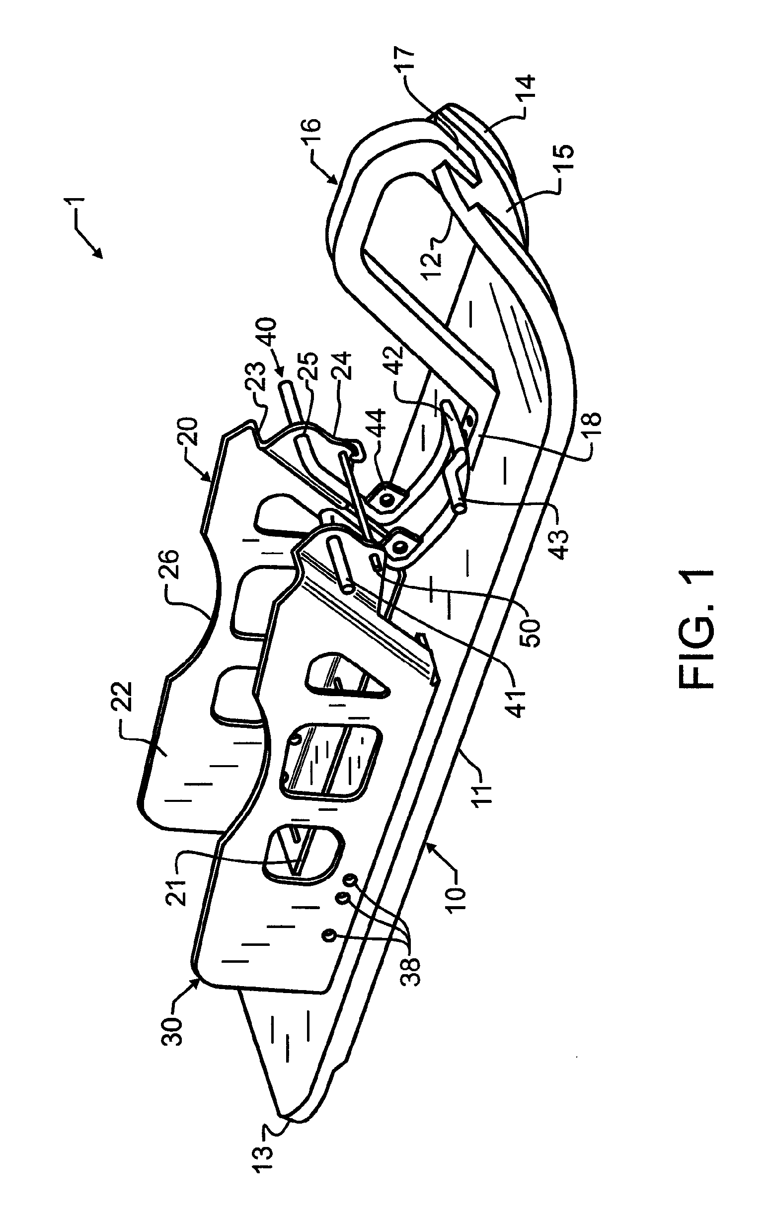
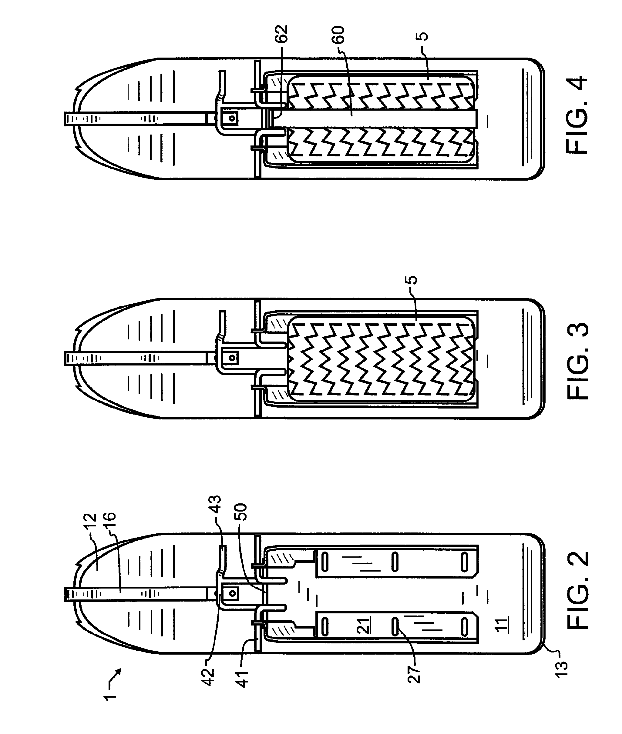
[0030]In a preferred embodiment of the invention illustrated in FIG. 1, a quick-release ATV ski 1 incorporates a ski-shaped wheel support 10 having a generally planar ski base 11, a raised leading tip 12, and a slightly raised trailing edge 13. Leading edge 12 is raised to float over the top of snow during forward travel, tending to drive the snow down under base 11. Since a driver may occasionally desire to back up, trailing edge 13 will also preferably have a slight raise above base 11, but ordinarily the reverse movement of ski 1 will be both slower and of shorter duration than forward movement, and so a much smaller elevation will be suitable for trailing edge 13 relative to leading edge 12. A lower surface of ski 1 does not have to be level, and as illustrated, inner bottom ski surface 15 is slightly elevated relative to outer bottom ski surfaces 14. Furthermore, there may optionally be one or more wear bars affixed to the bottom of ski 1, as is known in the snowmobile art.

[003...


PUM


Abstract

Quick-release skis couple to the front wheels of an ATV or other wheeled vehicle, to permit the ATV to travel over snow. The rear ATV wheels may be left unaltered, or more commonly, tracks may be substituted for the rear wheels. The ski coupling includes a drive-on runner and coupling having in one embodiment width-adjustable side walls, an over-center clamp, and a lock for securing the over-center clamp. In a second embodiment, a pivotal tire cage allows the ATV tire to be driven onto the ski, but simply by forward travel of the tire pivots to constrain the tire thereon. A strap then binds the tire and cage to ensure the tire stays in place on the ski. In a third embodiment, an ATV track is converted to a runner by the application and tensioning of a ski.

Description

CROSS REFERENCE TO RELATED APPLICATIONS[0001]This application claims priority to U.S. provisional patent application 61 / 326,217 filed Apr. 20, 2010 and naming the present inventor, the contents which are incorporated herein by reference in entirety.BACKGROUND OF THE INVENTION[0002]1. Field of the Invention[0003]This invention pertains generally to the field of motor vehicles, and more particularly to the provision of one or more ski-like or runner members substitutable for wheel type support structure. Closely related thereto in an alternative manifestation, this invention pertains generally to land vehicles, and more particularly to vehicles with runners applied to the wheels of wheeled vehicles.[0004]2. Description of the Related Art[0005]In many parts of the country, transportation is taken for granted. Through a vast network of paved and well-maintained roads and readily available and affordable automobiles and motorcycles, the vast majority of people are able to travel where th...

Claims


Application Information

Patent Timeline
IPC IPC(8): B62B19/02B62M27/02
CPCB62B19/02B62K5/01B62M2027/025B62M27/02B62M2027/021B62K13/00
Inventor RIVARD, GREGORY A.
Owner RIVARD GREGORY A
Learn More