
Multiuser MIMO system, receiver, and transmitter

a multi-user, multi-user technology, applied in the field of multi-user mimo systems, to achieve the effect of improving cell throughpu

Active Publication Date: 2011-10-20
GUANGDONG OPPO MOBILE TELECOMM CORP LTD
View PDF10 Cites 2 Cited by
  • Summary
  • Abstract
  • Description
  • Claims
  • Application Information

AI Technical Summary

Benefits of technology

[0025]As described above, the transmitter transmits a radio signal to the receiver according to any of claims 3 to 5 at the same time and at the same frequency as those of another transmitter in a transmission scheme different from that of the another transmitter, and therefore, it is possible to provide a radio communication system in which a receiver can separate a signal even in an environment in which transmitters that perform radio transmission in different transmission schemes exist mixedly.
[0026]According to the present invention, a plurality of transmitters performs radio transmission in different transmission schemes and at least one receiver receives a signal radio-transmitted from each transmitter and acquires data by separating the received signal for each transmitter, and therefore, it is possible to provide a radio communication system in which a receiver can separate a signal even in an environment in which transmitters that perform radio transmission in different transmission schemes exist mixedly. Hence, it is possible for each transmitter to determine a transmission scheme regardless of the transmission scheme of another transmitter. As a result, it is made possible to improve the cell throughput.

Problems solved by technology

However, the concept of the multiuser MIMO in the environment, in which each user uses different transmission schemes at the same time and at the same frequency, that is, the single-carrier and the multi-carrier exist mixedly, does not exist conventionally as a system.
On the other hand, in a band in which a certain user already performs the multi-carrier transmission, although it is required for another user to perform the multi-carrier transmission, however if the environment does not allow the multi-carrier transmission to be performed, the user has nothing to do but give up the communication itself in that band.

Method used


Image

  • Multiuser MIMO system, receiver, and transmitter
  • Multiuser MIMO system, receiver, and transmitter
  • Multiuser MIMO system, receiver, and transmitter

Examples


first embodiment

[0076]Next, embodiments according to the present invention will be described with reference to the drawings. In a first embodiment, an environment is supposed, in which each transmitter performs single-carrier transmission or multi-carrier transmission, and therefore, signals received by a receiver include single-carriers and multi-carriers mixedly in a multiuser MIMO system in which a plurality of transmitters accesses a base station at the same time and at the same frequency. The present invention realizes a communication system in which a signal of each user can be demultiplexed even in the environment described above.

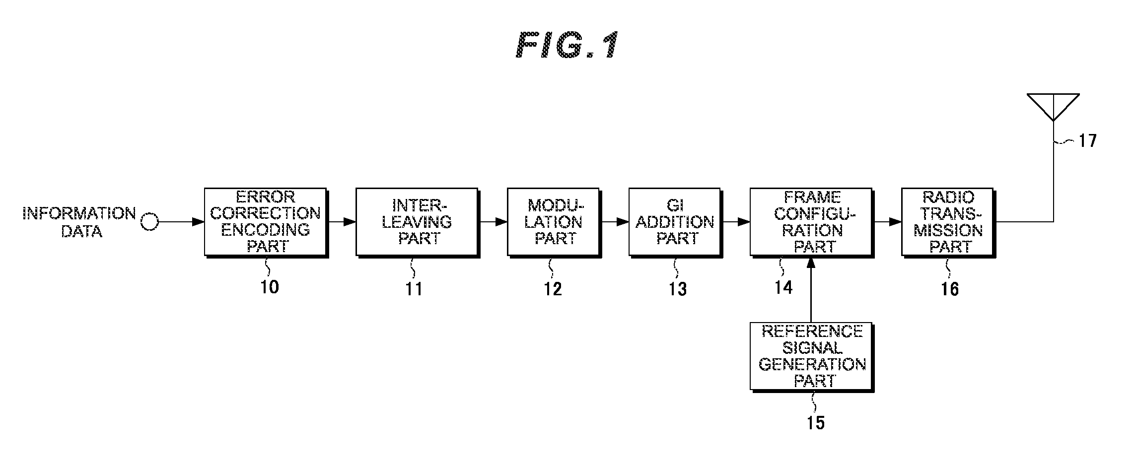
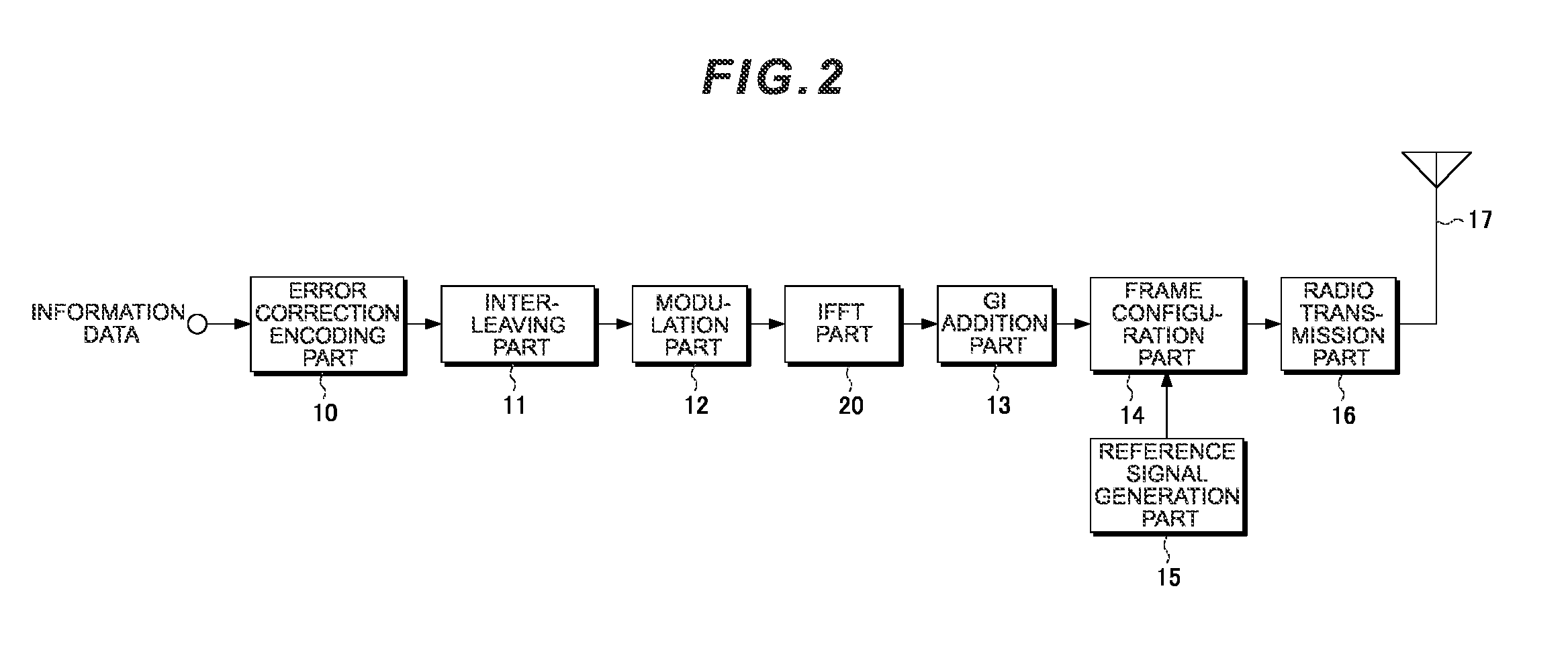
[0077]FIG. 1 is a diagram showing a schematic configuration of a transmitter that performs single-carrier transmission. The single-carrier transmission includes various types, however, in this specification, the single-carrier transmission is defined as a transmission scheme in which a single is generated in a time domain and the multi-carrier transmission as a tran...

second embodiment

[0101]In the above-described first embodiment, the case where all of the spectra of respective users overlap is explained, however, in a second embodiment, a case is explained, where MIMO multiplexing is performed only in a certain partial spectrum. Further, in the second embodiment, explanation is given using Clustered DFT-S-OFDM as single-carrier transmission and OFDM that uses a discontinuous band as multi-carrier transmission, however, the present invention can be embodied also when other systems are used.

[0102]FIG. 9 is a diagram showing a schematic configuration of a transmitter that performs Clustered DFT-S-OFDM transmission. The configuration differs from that of the transmitter that performs single-carrier transmission shown in FIG. 1 only in that a DFT part 90, a spectrum mapping part 91, and an IFFT part 92 are inserted between the modulation part 12 and the GI addition part 13.

[0103]The output of the modulation part 12 is input to the DFT part 90. The DFT part 90 applies...


PUM


Abstract

Even when respective transmitters use different transmission schemes, signals of the respective transmitters are separated. A receiver that is applied to a multiuser MIMO system in which a plurality of transmitters performs transmission to at least one receiver, includes a MIMO separation part 40 that receives signals transmitted in different transmission schemes at the same time and at the same frequency and separates the received signals for each transmitter, a switching part 41 that switches output destinations according to the transmission scheme of the separated signal, and a single-carrier processing part 42 and a multi-carrier processing part 43 provided for each transmission scheme for processing a signal output from the switching part 41 according to its transmission scheme.

Description

TECHNICAL FIELD[0001]The present invention relates to a multiuser MIMO system in which a plurality of transmitters performs transmission to at least one receiver, and relates to a receiver and a transmitter used in the system.BACKGROUND ART[0002]In the next generation mobile communication, a high-speed data transmission is demanded. In order to perform a high-speed data transmission, a wide frequency band is necessary. However, in a radio communication channel, frequency selective fading including a number of delayed waves (multi-paths) occurs. When performing a wideband single-carrier transmission in such a communication environment, the sampling intervals of received signals become shorter, and therefore, the delayed wave in the channel causes inter-symbol interference, resulting in considerable deterioration in the transmission performances. There is a technique to suppress the inter-symbol interference by time domain signal processing, however, there is such a problem that the c...

Claims


Application Information

Patent Timeline
Patent Type & Authority Applications(United States)
IPC IPC(8): H04L1/02H04L27/04H04L27/06
CPCH04B7/0452H04J11/0026H04J11/0046H04L27/265H04L27/2636H04W72/00H04L25/0242H04L27/26526H04B7/0854
Inventor NAKAMURA, OSAMUURABE, SHUUJIHAMAGUCHI, YASUHIROYOKOMAKURA, KAZUNARIGOTO, JUNGOTAKAHASHI, HIROKI
Owner GUANGDONG OPPO MOBILE TELECOMM CORP LTD
Learn More