Signal separating system

a separation system and signal technology, applied in the field of signal separation system, can solve the problems of difficult monitoring unknown pulsed emission or continuous wave (cw) emissions, settling time which can be too slow to remove fast agile, and is not readily adaptable to remove multiple cw spread spectrum interfering, etc., to achieve enhanced performance, reduce or minimise frequency obstruction, and enhance signal to noise

Inactive Publication Date: 2004-10-07
ASTRIUM GMBH
View PDF11 Cites 1 Cited by
  • Summary
  • Abstract
  • Description
  • Claims
  • Application Information

AI Technical Summary

Benefits of technology

[0004] It is an object of the present invention to provide an improved signal separating system which has a virtually zero settling time response, which is unaffected by multipath effects / amplitude variations and which has the capability of instantly separating known transmission interference from unknown signal emissions, for example radar signal emissions, and of monitoring and optionally enhancing the unknown signal emission characteristics within the same bandwidth as the known own emissions without interference.
[0029] Further, signal separation in the system of the invention can be effectively carried out with pulse or CW unknown and known signal combinations using modulated or unmodulated signals.

Problems solved by technology

Monitoring unknown pulsed emissions or continuous wave (CW) emissions is difficult in the presence of high level CW emissions in the monitored bandwidth.
Further, adaptive filters, for example adaptive YIG filters, have settling times which can be too slow to remove fast agile signal emissions such as very fast frequency hopped CW wideband communications emissions and are not readily adaptable to remove multiple CW spread spectrum interfering emissions.

Method used


Image

  • Signal separating system
  • Signal separating system
  • Signal separating system

Examples


Embodiment Construction

[0039] In this specification, the term "frequency agile" is taken to mean or cover any form of signal which can move across the frequency band by changing its frequency.

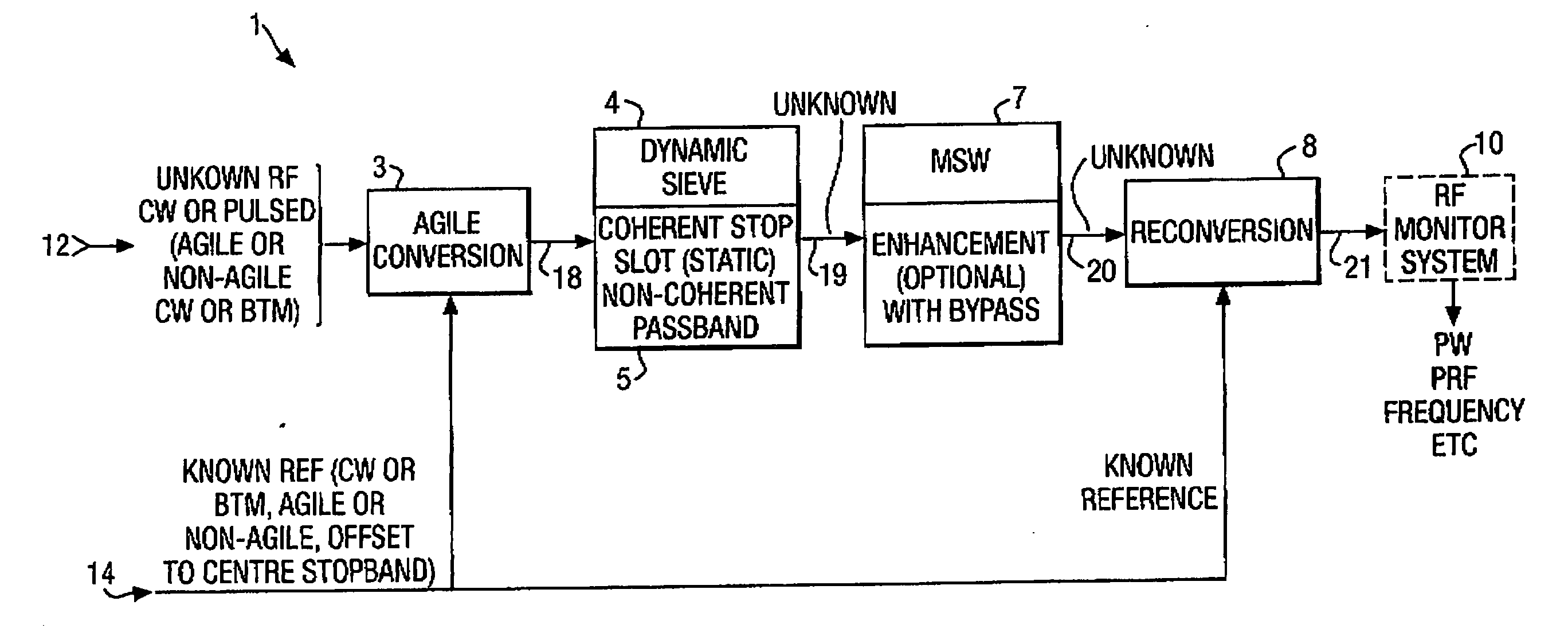
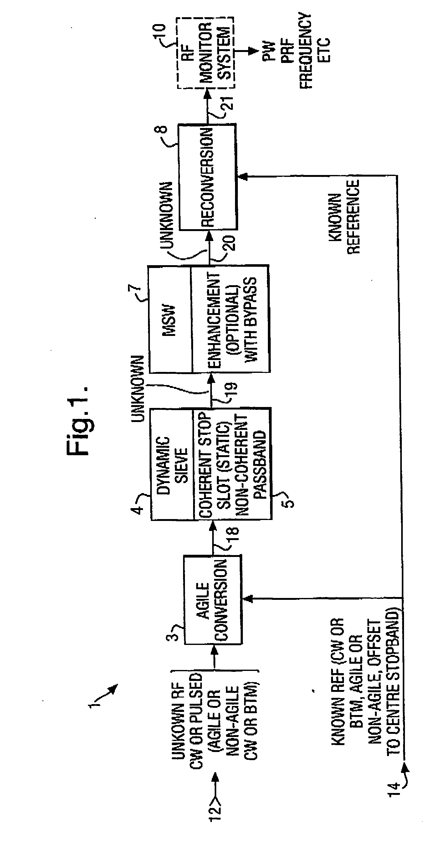
[0040] Referring first to FIG. 1, there is schematically shown a preferred signal separating apparatus 1 embodying the present invention. The signal separating apparatus 1 comprises an agile frequency conversion element 3, a frequency filter 4 with an associated coherent frequency stop slot 5 and non-coherent frequency passband 5, a magnetostatic wave (MSW) enhancer 7 with bypass and a frequency reconversion element 8.

[0041] As shown in FIG. 1, the agile frequency conversion element 3 receives and combines at is input side (i) an incident mixed signal 12 comprising known and unknown signal components and (ii) a known control reference signal 14. The input signal is frequency converted by the conversion element 3 and the resultant frequency converted signal 18 is output to the connecting frequency filter 4. The freque...


PUM


Abstract

A signal separating system 1 comprises a frequency conversion element 3, a dynamic filter component 4 with associated coherent stop slot and non-coherent passband, optionally a signal wave enhancer 7 with bypass, and a frequency reconversion element 8. In operation of the system, mixed incoming signals 12 (CW or pulse signals) having known interference and unknown emission components can be effectively separated, permitting a virtually instantaneous separation of the known interference from the unknown emissions and permitting an unobscured monitoring and / or characterisation of the extracted unknown emissions 21, if desired. The arrangement bears definite advantage over known arrangements and retains utility for various frequency / agile or multiple or non-agile unknown signal applications.

Description

[0001] The present invention relates to a signal separating system and more particularly, but not exclusively, concerns a signal separating method and apparatus for separating known transmission interference from unknown radar signal emissions.[0002] Monitoring unknown pulsed emissions or continuous wave (CW) emissions is difficult in the presence of high level CW emissions in the monitored bandwidth. Pulsed emission monitoring in the presence of pulsed interference can be overcome using established pulse on pulse extraction techniques but CW high level interference tends to mask unknown low level pulses within the monitored bandwidth. In the past, static or adaptive filters have been used to remove CW interference, creating blind spots in the monitored bandwidth. Further, adaptive filters, for example adaptive YIG filters, have settling times which can be too slow to remove fast agile signal emissions such as very fast frequency hopped CW wideband communications emissions and are n...

Claims


Application Information

Patent Timeline
Patent Type & Authority Applications(United States)
IPC IPC(8): G01S7/02G01S7/03G01S7/292G01S7/36
CPCG01S7/021G01S7/032G01S7/292G01S7/36
Inventor NENDICK, VICTOR
Owner ASTRIUM GMBH
Why Eureka
Try Eureka