

Connector
- Summary
- Abstract
- Description
- Claims
- Application Information
AI Technical Summary
Benefits of technology
Problems solved by technology
Method used
Image

Examples
Embodiment Construction
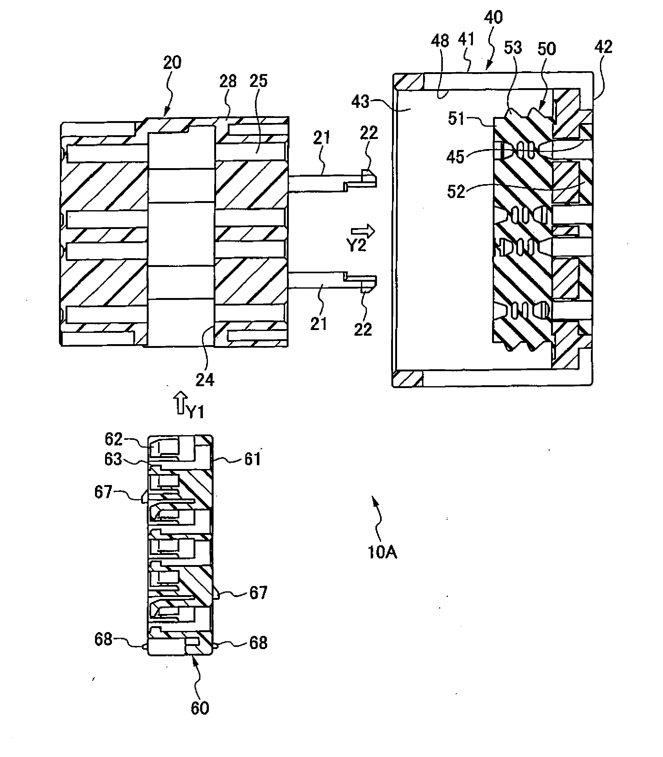
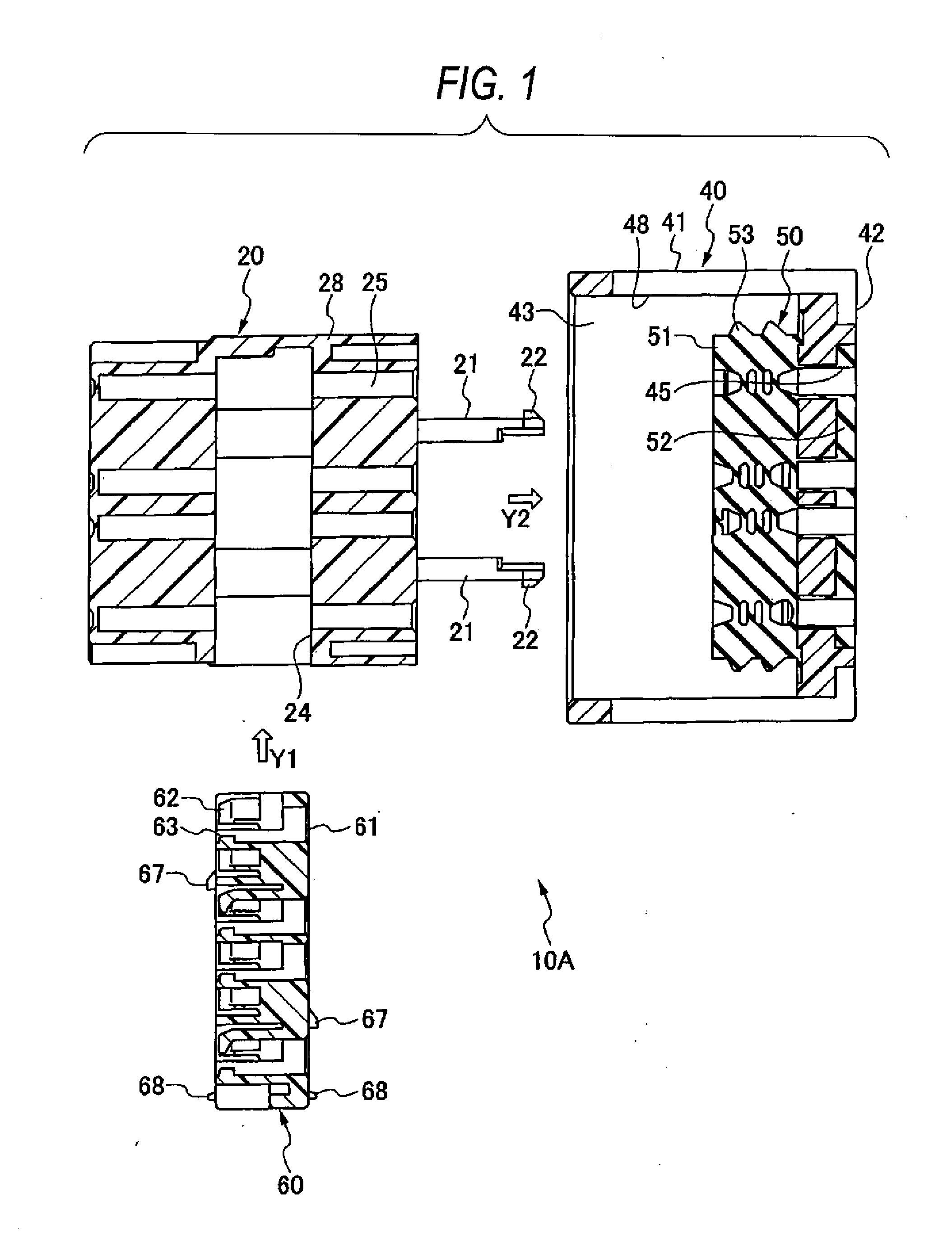
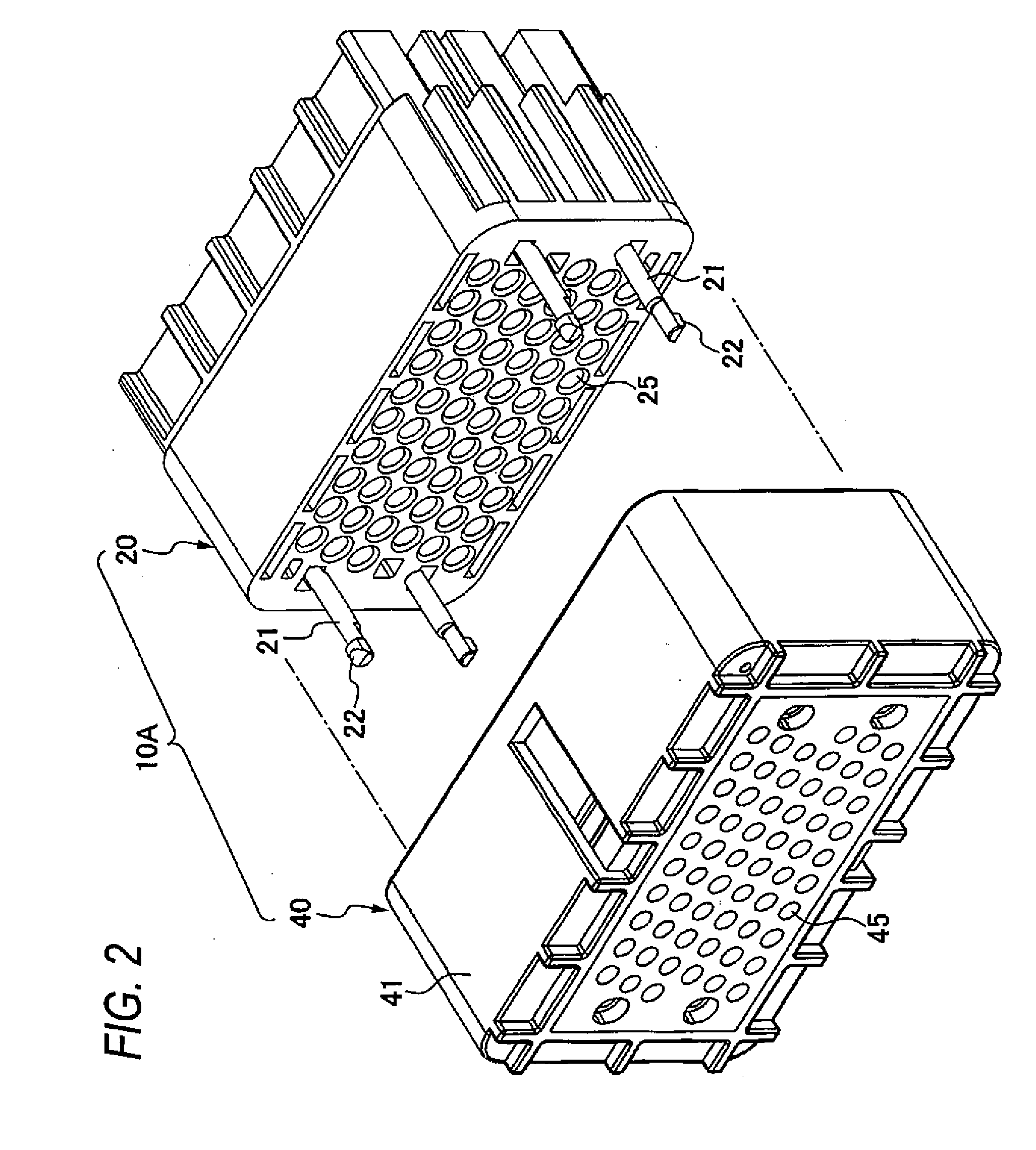
[0048]Now, an exemplary embodiment of the present invention will be described below by referring to the drawings.
[0049]FIG. 1 is a side sectional view showing a relation between an inner housing 20, an outer housing 40 and a spacer 60 which form a connector housing 10A of a connector of an exemplary embodiment. FIG. 2 is a perspective view showing a relation between the inner housing 20 and the outer housing 40. FIG. 3 is a partly broken perspective view showing the inner housing 20 and the outer housing 40. FIG. 4 is a side sectional view showing a state that the inner housing 20 with which the spacer 60 is temporarily engaged is attached to the outer housing 40. FIG. 5 is partly broken perspective view showing the state illustrated in FIG. 4. FIG. 6 is a front view of the spacer 60. FIG. 7 is a partly enlarged view of FIG. 6. FIG. 8 is a perspective view of the spacer 60 seen from a front surface side. FIG. 9 is a partly enlarged view of FIG. 8. FIG. 10 is a perspective view seen ...
PUM
 Abstract
Description
Claims
Application Information