Forging die holder

a technology of forging dies and holder plates, which is applied in forging/pressing/hammering apparatus, forging/hammering/pressing machines, and shaping tools, etc., can solve the problems of reducing the foregoing press load placed, less readily and more slowly transferring heat generated by resistance heaters to the dies in the middle portion of the forging die holder, and the resistance heaters cannot efficiently heat the dies to predetermined temperature, etc., to achieve efficient hea

Active Publication Date: 2011-10-27
KOBE STEEL LTD
View PDF9 Cites 7 Cited by
  • Summary
  • Abstract
  • Description
  • Claims
  • Application Information

AI Technical Summary

Benefits of technology

[0027]In the forging die holder according to the second aspect of the present invention, the heater mounting hole is formed at the position between the plurality of dies in aligned relation with the side surfaces of each of dies. This allows the resistance heater to be disposed at a position in the vicinity of each of the dies. Accordingly, due to the distance by which the resistance heater is disposed closer to each of the dies, each of the dies can be preheated more swiftly to a predetermined temperature appropriate for performing warm forging or hot forging and held at the temperature.
[0028]In the forging die holder according to the third aspect of the present invention, the resistance heater formed of the rod-like heater is inserted into the heater mounting hole formed to extend from the front surface of the die holder to the rear surface thereof. This allows the whole die to be efficiently heated.
[0029]In the forging die holder according to the fourth aspect of the present invention, the resistance heater is formed of the rod-like multi-cell heater in which the plurality of heaters are connected in the longitudinal direction. This allows the die to be heated to desired temperatures suited to the individual portions of the die. As a result, it is possible to preheat or heat the whole die to an optimum temperature for performing warm forging or hot forging.
[0030]In the forging die holder according to the fifth aspect of the present invention, by inserting the resistance heaters into the plurality of heater mounting holes arranged in the vertical direction, the whole die holder can be swiftly heated to be able to efficiently preheat the die held in the die holder or retain the temperature thereof.
[0031]In the forging die holder according to the sixth aspect of the present invention, the sensor mounting hole is disposed generally in the middle of the plurality of resistance heaters. This allows the temperature at the middle of the portion heated with the plurality of resistance heaters to be measured. Therefore, the temperature of the die can be accurately measured. As a result, the heated temperature or the preheated temperature can be efficiently and accurately measured even with the one temperature sensor disposed at the middle. In addition, since the number of the temperature sensors is small, the number of assembly steps and the number of parts can be reduced.
[0032]In the forging die holder according to the seventh aspect of the present invention, the lead wires of the plurality of resistance heaters can be routed in the bundled state. Therefore, a wiring operation for the resistance heaters can be simplified.

Problems solved by technology

This can reduce the foregoing press load placed on the resistance heaters but, due to the distance by which the resistance heaters are apart from the dies, heat generated from the resistance heaters is less readily and more slowly transmitted to the dies in the middle portion of the die holder.
As a result, a problem arises that the resistance heaters cannot efficiently heat the dies to predetermined temperatures via the die holder to perform preheating or heat retention.
Even if the temperature sensors can detect the temperatures of the heated portions of the die holder heated with the resistance heaters, since the temperature measurement is performed at the positions apart from the dies in the middle portion of the die holder, a problem also arises that the preheated temperatures of the dies before warm forging or hot forging is performed and the temperatures at which the dies are held during forging cannot be accurately measured.

Method used


Image

  • Forging die holder
  • Forging die holder
  • Forging die holder

Examples


Embodiment Construction

[0040]Referring now to the drawings, an embodiment for practicing the invention will be described hereinbelow.

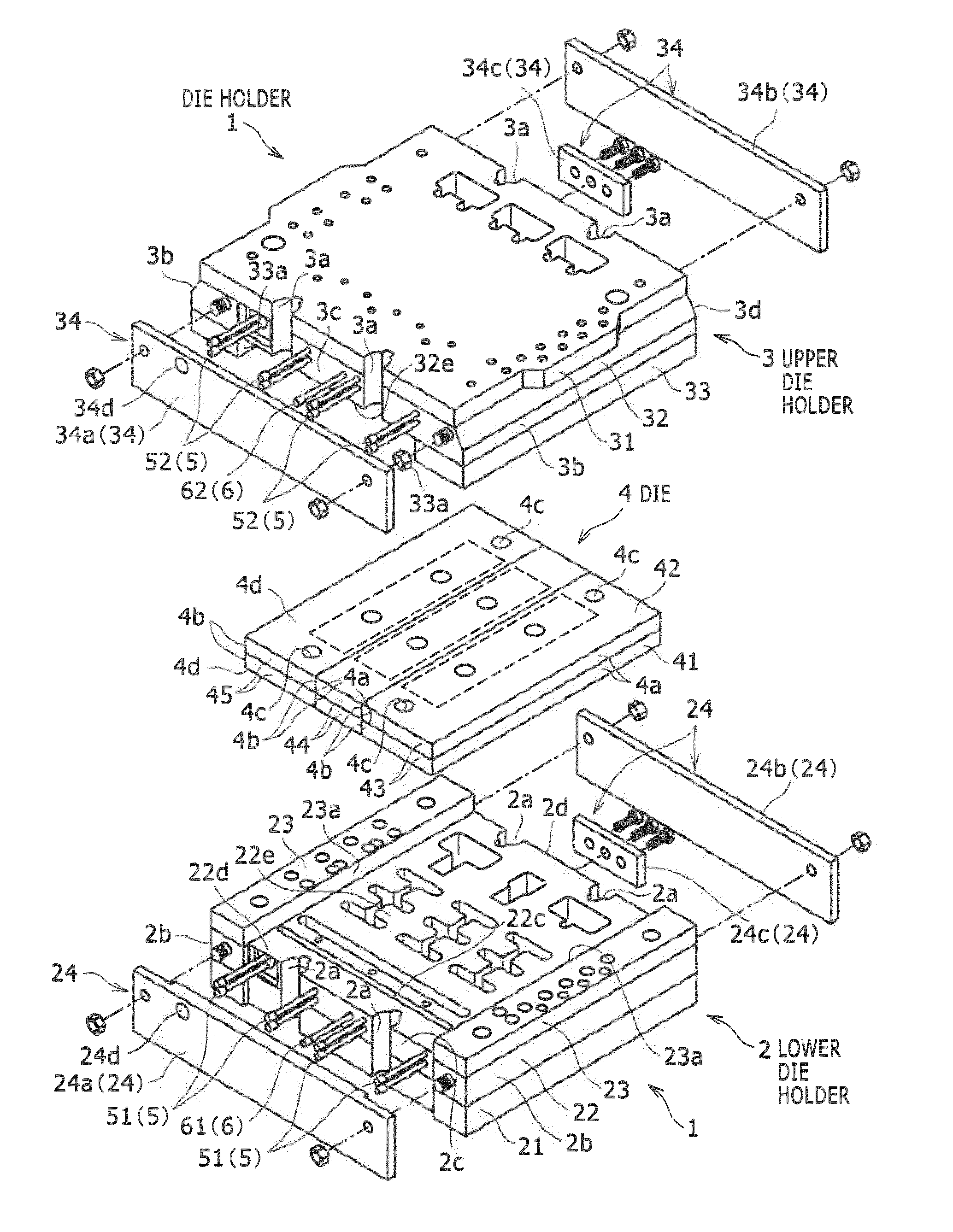
[0041]Note that the direction in which a die holder 1 (forging die holder) is installed and the direction in which the die holder 1 is driven can be changed as necessary by changing the directions in which a lower die 41 and an upper die 42 of a forging press P shown in FIG. 1 and the like are installed, but a description will be given by using, as an example, the case where the upper die 42 moves in a vertical direction and assuming that a front-to-rear direction and a left-to-right direction in the drawings correspond to the vertical direction and a lateral direction for the sake of convenience.

[0042]Prior to the description of the die holder 1, the forging press P to which the die holder 1 is attached and a die 4 held by the die holder 1 will be described.

[0043]>

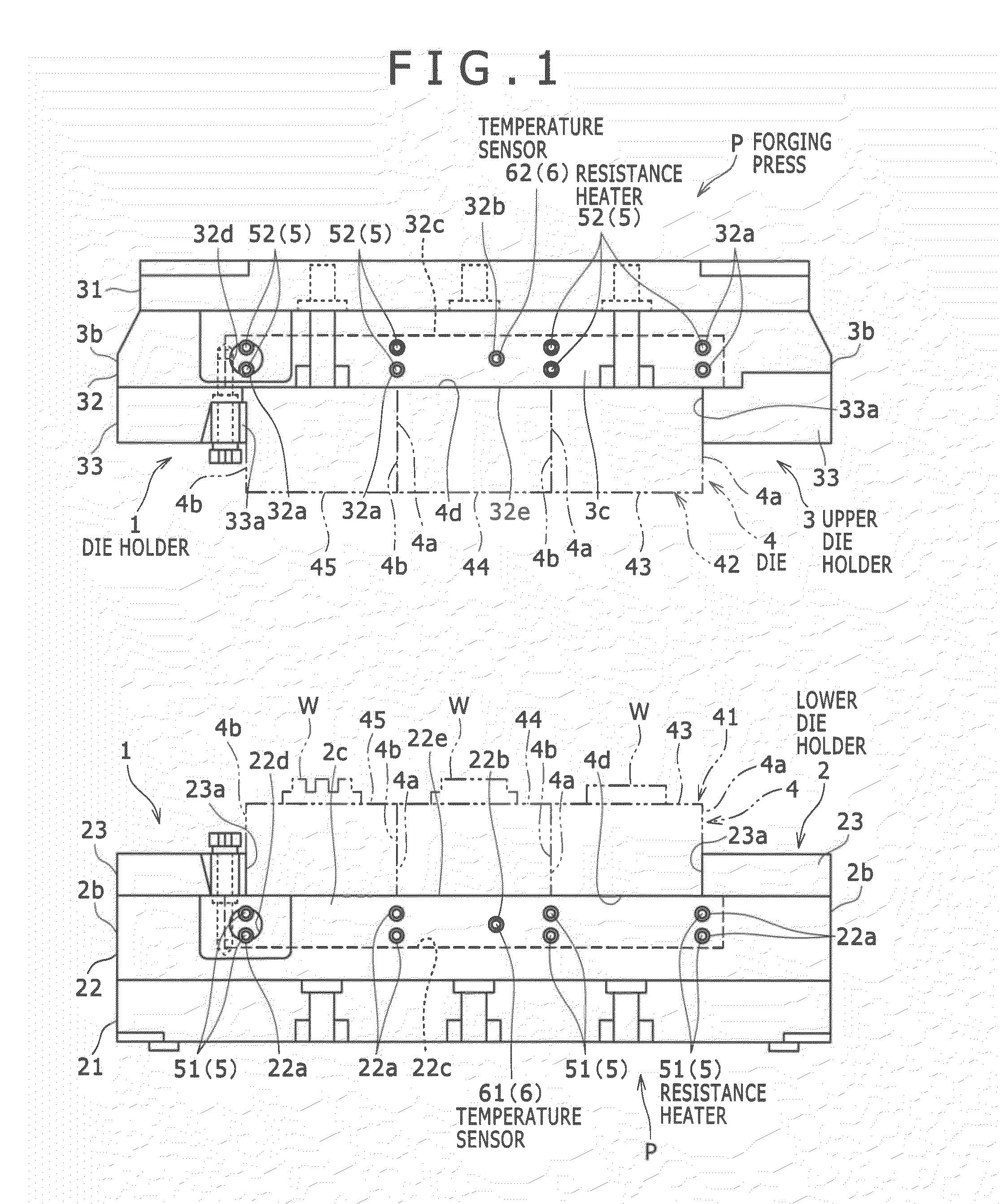
[0044]As shown in FIG. 1, the forging press P is a vertical multi-step forging pressing machine (forging die ap...


PUM

PropertyMeasurementUnit
diametersaaaaaaaaaa
plastic deformabilityaaaaaaaaaa
temperatureaaaaaaaaaa

Abstract

There is provided a forging die holder including a resistance heater capable of efficiently heating a die via the die holder when warm forging or hot forging is performed. A die holder is for holding a die used in a forging press for performing warm forging or hot forging. The die holder has heater mounting holes into which resistance heaters are inserted, sensor mounting holes into which temperature sensors are inserted, and guide portions disposed on both end portions of holder surfaces of holders for supporting back surfaces of the foregoing die to support side surfaces of the foregoing die located therebetween on both sides thereof. The heater mounting holes are formed at positions opposing the holder surfaces in aligned relation with the side surfaces of the foregoing die.

Description

FIELD OF THE INVENTION[0001]The present invention relates to a forging die holder used to hold a die when a forging raw material is subjected to warm forging or hot forging using a forging press.BACKGROUND OF THE INVENTION[0002]Conventionally, when a forging raw material in a preheated state is subjected to warm forging or hot forging using a forging press, forging is performed by preheating forging dies and also a forging die holder holding the dies so as not to degrade the plastic deformability of the forging raw material (see, e.g., Japanese Unexamined Patent Application Publication No. Hei 08 (1996)-206768 (FIGS. 1, 2A, and 2B)).[0003]In the forging die holder described in Japanese Unexamined Patent Application Publication No. Hei 08 (1996)-206768 (FIGS. 1, 2A, and 2B) mentioned above, a plurality of parallel grooves each having a U-shaped cross-sectional shape are formed in the longitudinal side surfaces of the die holder, and resistance heaters (sheathed heaters) each formed o...

Claims


Application Information

Patent Timeline
Patent Type & Authority Applications(United States)
IPC IPC(8): B21J13/03
CPCB21J13/03B21J1/06
Inventor ITO, MASAMITANAHASHI, MASANORINAKANISHI, HIROYUKI
Owner KOBE STEEL LTD
Why Eureka
Try Eureka