Valve timing control apparatus

Active Publication Date: 2011-10-27
TOYOTA JIDOSHA KK
View PDF3 Cites 33 Cited by
  • Summary
  • Abstract
  • Description
  • Claims
  • Application Information

AI Technical Summary

Benefits of technology

[0010]The present invention is made in view of the above disadvantages. According to the present invention, there is provided a valve timing control apparatus for an internal combustion engine. The valve timing control apparatus is supplied with hydraulic fluid from a supply source upon rotation of the internal combustion engine to control valve timing of a valve, which is opened or closed by a camshaft that is, in turn, driven by a torque transmitted from a crankshaft of the internal combustion engine. The valve timing control apparatus includes a housing, a vane rotor, a primary limiting member, a primary resilient member, a secondary limiting member and a secondary resilient member. The housing is adapted to be driven together with the crankshaft and includes a recess, which is recessed in an inner surface of the housing. The vane rotor includes a vane and a receiving hole. The vane partitions between an advancing chamber and a retarding chamber in an inside of the housing. The receiving hole forms a working chamber therein. The vane rotor is adapted to be rotated together with the camshaft and is rotatable relative to the housing to change a rotational phase toward a corresponding one of an advancing side and a retarding side when the hydraulic fluid is supplied into a corresponding one the advancing chamber and the retarding chamber. The primary limiting member is received in the receiving hole and is slidable in both of an inserting direction toward the surface of the housing and a removing direction away from the surface of the housing. The primary limiting member limits the rotational phase to a limited phase, which is between a most advanced phase and a most retarded phase, when the primary limiting member is inserted into the recess in the inserting direction. The primary limiting member enables release of the rotational phase from the limited phase when the primary limiting member is removed from the recess in the removing direction. The primary resilient member urges the primary limiting member in the inserting direction. The primary resilient member urges the primary limiting member into the recess in the inserting direction in a state where the rotational phase is the limited phase. The primary resilient member urges

Problems solved by technology

Therefore, under the low temperature environment, in which the viscosity of the working fluid is increased, the movement of the limiting member into the recess cannot be made in time, so that the startability of the engine is disadvantageously deteriorated.
In the case of the above construction, when the slide gap between each of the primary and secondary limiting members and the receiving hole and the slide gap between the primary limiting member and the secondary limiting member are both increased, the correct orientation of each of the primary and secondary limiting members cannot be maintained, so that the primary limiting member may possibly be tilted or may experience an inserting malfunction (i.e., the primary limiting member being not appropriatel

Method used


Image

  • Valve timing control apparatus
  • Valve timing control apparatus
  • Valve timing control apparatus

Examples


Embodiment Construction

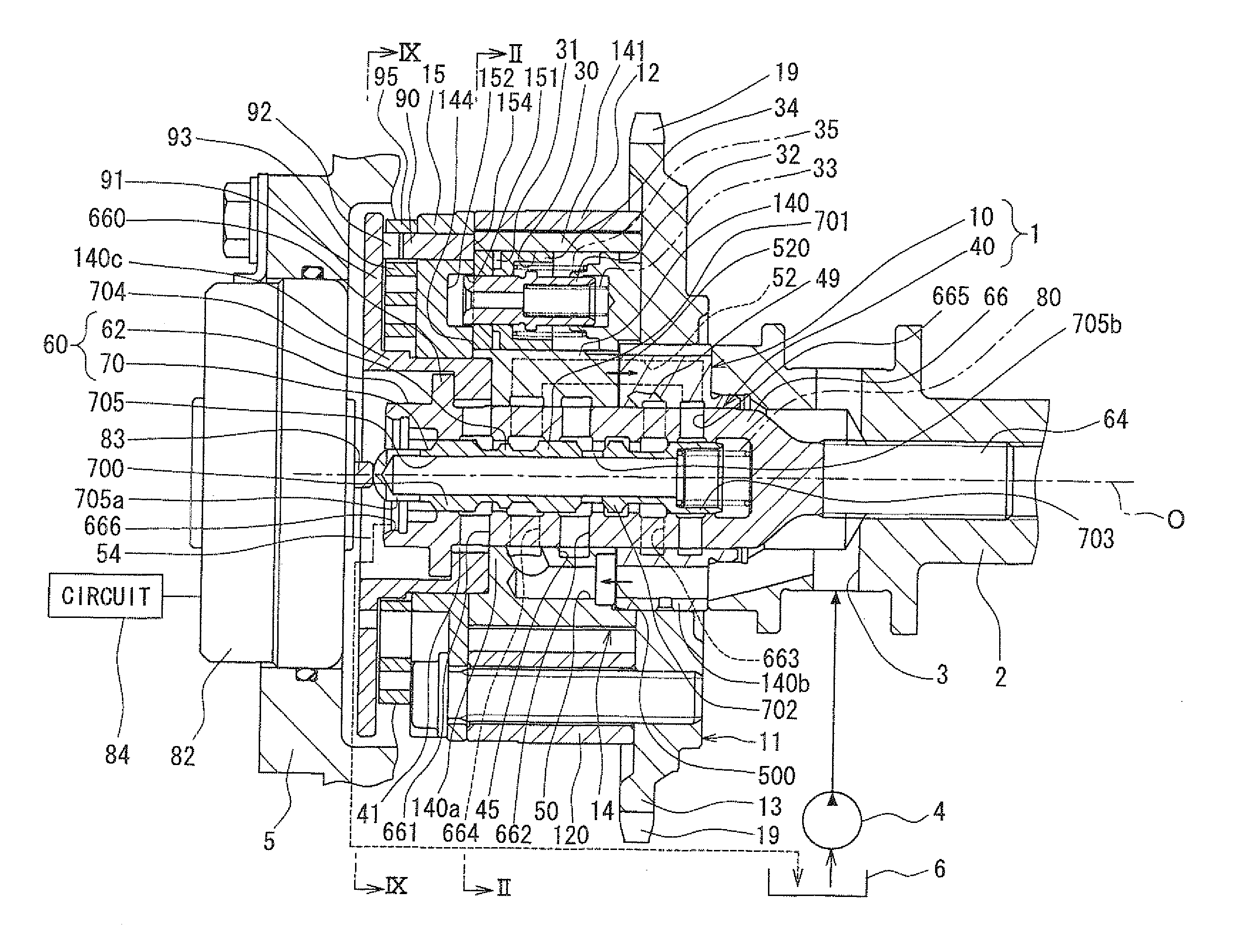
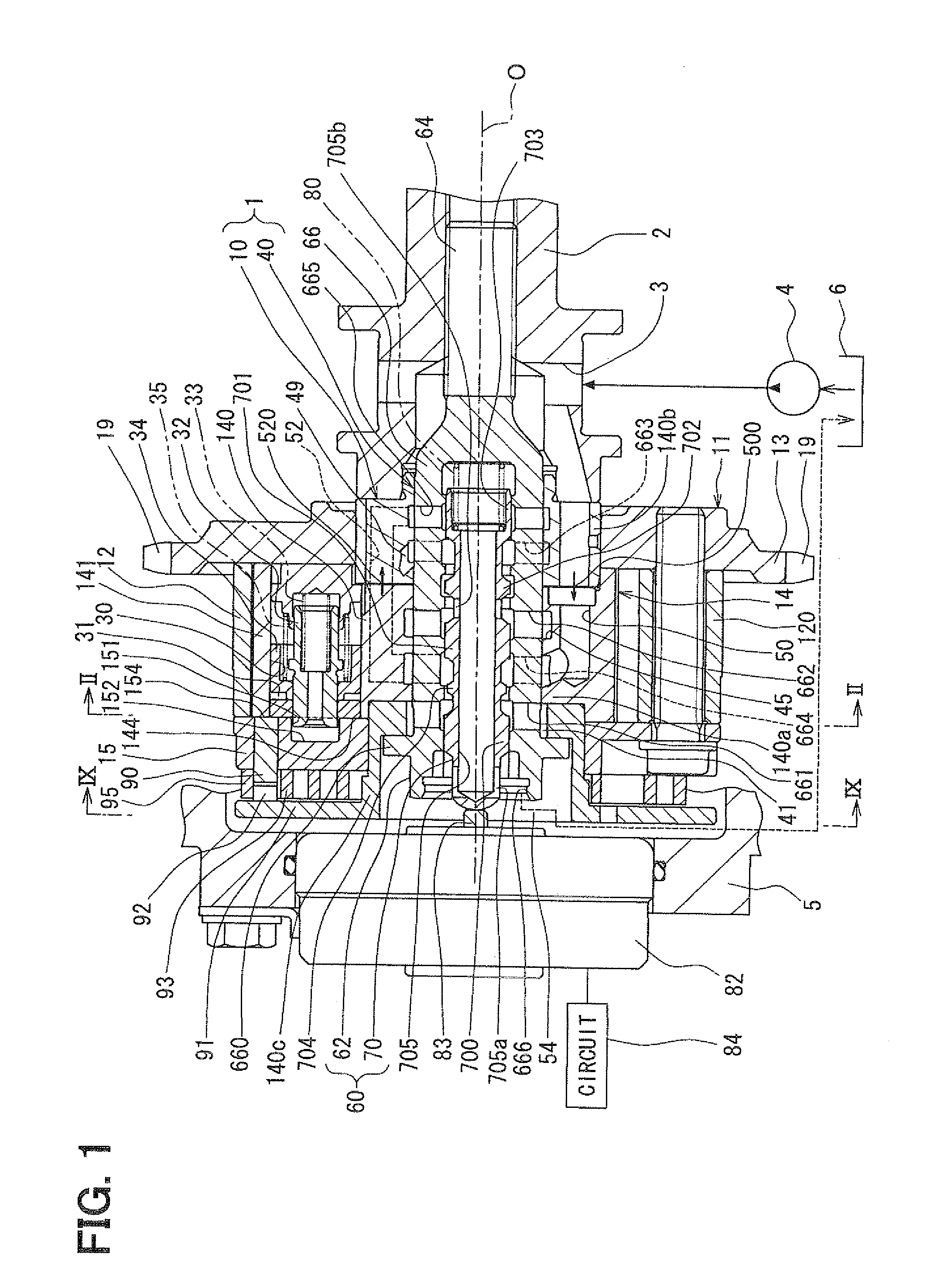
[0028]An embodiment of the present invention will be described with reference to the accompanying drawings. FIG. 1 shows a valve timing control apparatus 1 of the present embodiment installed to an internal combustion engine of a vehicle (more specifically, an automobile). The valve timing control apparatus 1 controls valve timing of an intake valve (serving as a drive-subject valve or simply referred to as a valve) through use of hydraulic oil (serving as hydraulic fluid). The valve timing control apparatus 1 includes a drive device 10 and a control device 40. The drive device 10 is placed in a transmission system, which transmits an engine torque from a crankshaft (not shown) to a camshaft 2. The drive device 10 is driven by the hydraulic oil. The control device 40 controls the supply of the hydraulic oil to the drive device 10.

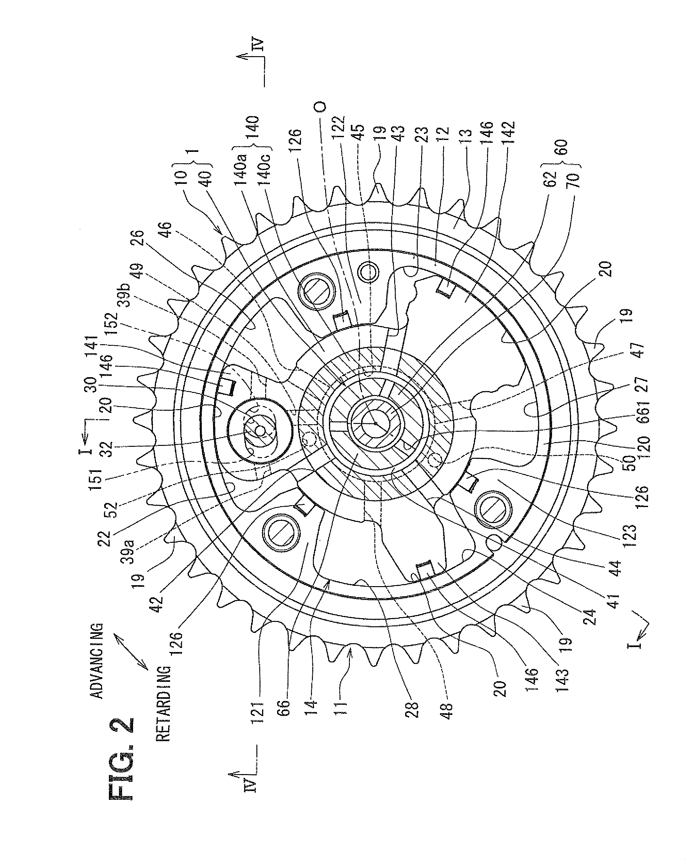
[0029]In the drive device 10 shown in FIGS. 1 and 2, a housing 11 includes a shoe housing 12, a sprocket 13 and a front plate 15.

[0030]The shoe housing 12 ...


PUM


Abstract

A primary resilient member urges a primary limiting member into a recess in an inserting direction in a state where a rotational phase is a limited phase in a limited phase range. A relative slide gap is radially provided between the primary limiting member and a secondary limiting member at a location adjacent to a working chamber. First and second primary slide gaps are radially provided between the primary limiting member and radially opposed wall surface sections of the receiving hole. A secondary slide gap is radially provided between the secondary limiting member and a radially opposed wall surface section of the receiving hole. The relative slide gap is larger than the first and second primary slide gaps and the secondary slide gap.

Description

CROSS REFERENCE TO RELATED APPLICATION[0001]This application is based on and incorporates herein by reference Japanese Patent Application No. 2010-101170 filed on Apr. 26, 2010.BACKGROUND OF THE INVENTION[0002]1. Field of the Invention:[0003]The present invention relates to a valve timing control apparatus, which controls valve timing of a valve that is opened or closed by a camshaft through transmission of a torque from a crankshaft of an internal combustion engine.[0004]2. Description of Related Art:[0005]A previously known valve timing control apparatus includes a housing, which is rotated together with a crankshaft, and a vane rotor, which is rotated together with the camshaft. This valve timing control apparatus controls the valve timing through use of hydraulic fluid, which is supplied from a supply source (e.g., a pump) upon rotation of the engine. For instance, the valve timing is controlled by changing a rotational phase of the vane rotor toward an advancing side or a retar...

Claims


Application Information

Patent Timeline
IPC IPC(8): F01L1/34
CPCF01L1/3442F01L2001/34426F01L2001/3443F01L2800/01F01L2001/34476F01L2001/34483F01L2250/02F01L2001/34469
Inventor FUJIYOSHI, TOSHIKI
Owner TOYOTA JIDOSHA KK
Why Eureka
Try Eureka