
Gripping device for gripping underwater pipelines at the laying stage, and relative auxiliary gripping tool

a technology of underwater pipelines and gripping devices, which is applied in the direction of pipe laying and repair, transportation and packaging, load-engaging elements, etc., can solve the problems of increasing the size of the jaws, the physical limits of the pressure limit, and the inability to grip the pipeline at the laying stage, so as to achieve the effect of increasing the grip

Active Publication Date: 2011-10-27
SAIPEM SPA
View PDF6 Cites 2 Cited by
  • Summary
  • Abstract
  • Description
  • Claims
  • Application Information

AI Technical Summary

Benefits of technology

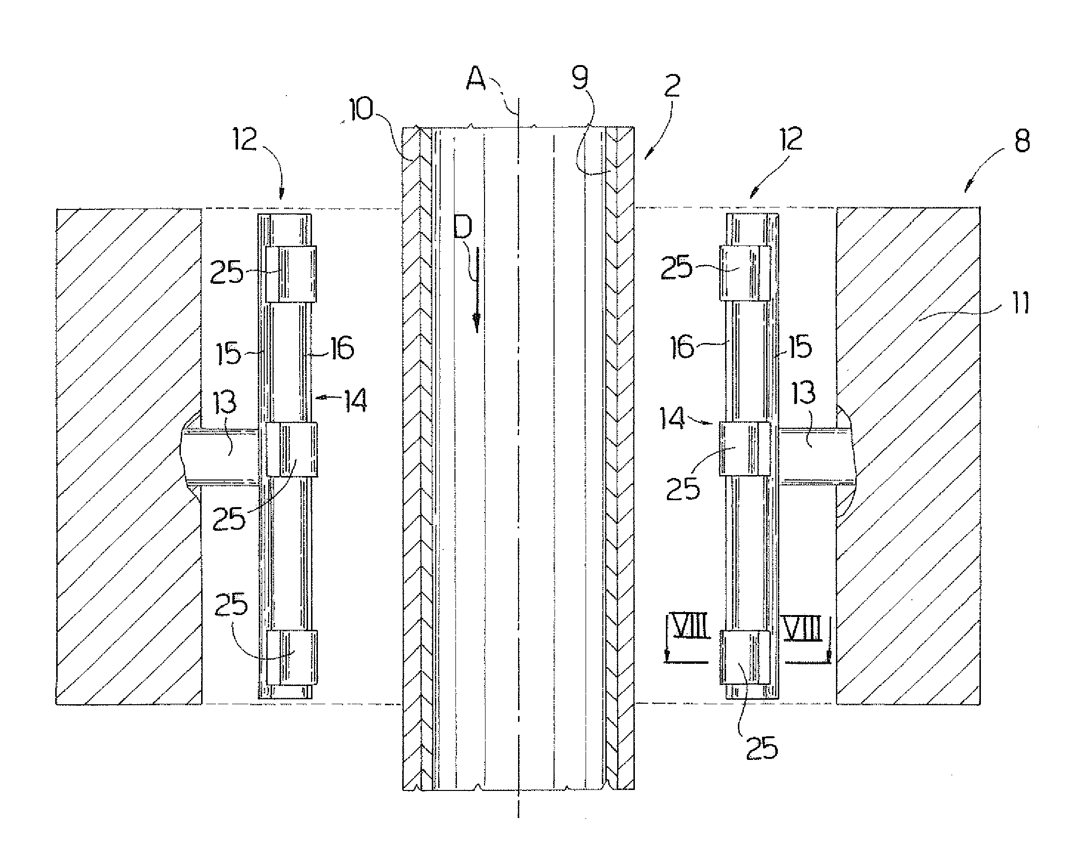
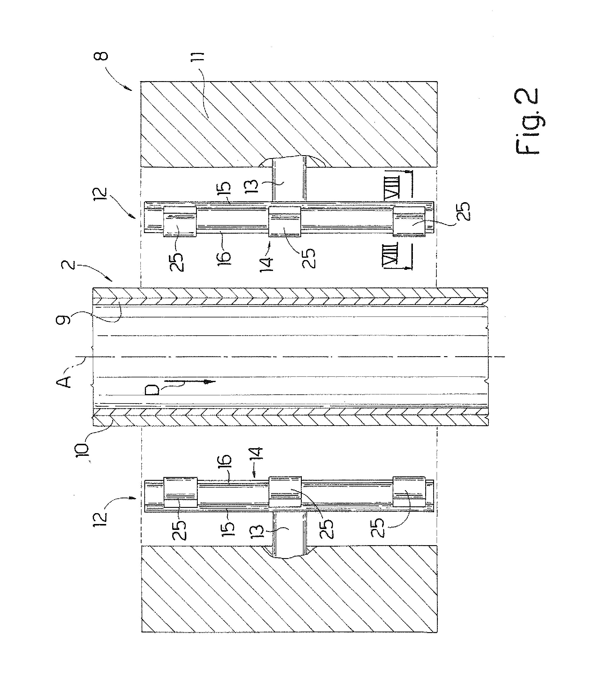
The present invention provides an underwater-pipeline gripping device that is versatile and provides for firm, precise grip. The device includes jaws that are pressed onto a pipeline extending along an axis substantially parallel to a laying direction. Each jaw comprises a friction pad that is brought cyclically into contact with the outer face of the pipeline. An auxiliary gripping tool is selectively connectable to the jaw to increase grip between the friction pad and the pipeline. The interface between the friction pad and the pipeline can be modified as a function of operating conditions, making the device highly versatile. The invention also provides an auxiliary gripping tool for a gripping device for gripping underwater pipelines at the laying stage.

Problems solved by technology

There is a limit, however, to the pressure that can be exerted by the jaws on the pipeline without damaging the pipeline at the grip area.
Many operating conditions therefore call for increasing the size of the jaws, but even this has its physical limits.
This technique is not without its drawbacks, however, such as rapid deterioration of the friction pads caused by including the metal bosses, and the very real risk, in some cases, of damaging the protective coating of the pipeline.

Method used


Image

  • Gripping device for gripping underwater pipelines at the laying stage, and relative auxiliary gripping tool
  • Gripping device for gripping underwater pipelines at the laying stage, and relative auxiliary gripping tool
  • Gripping device for gripping underwater pipelines at the laying stage, and relative auxiliary gripping tool

Examples


Embodiment Construction

The Laying Vessel

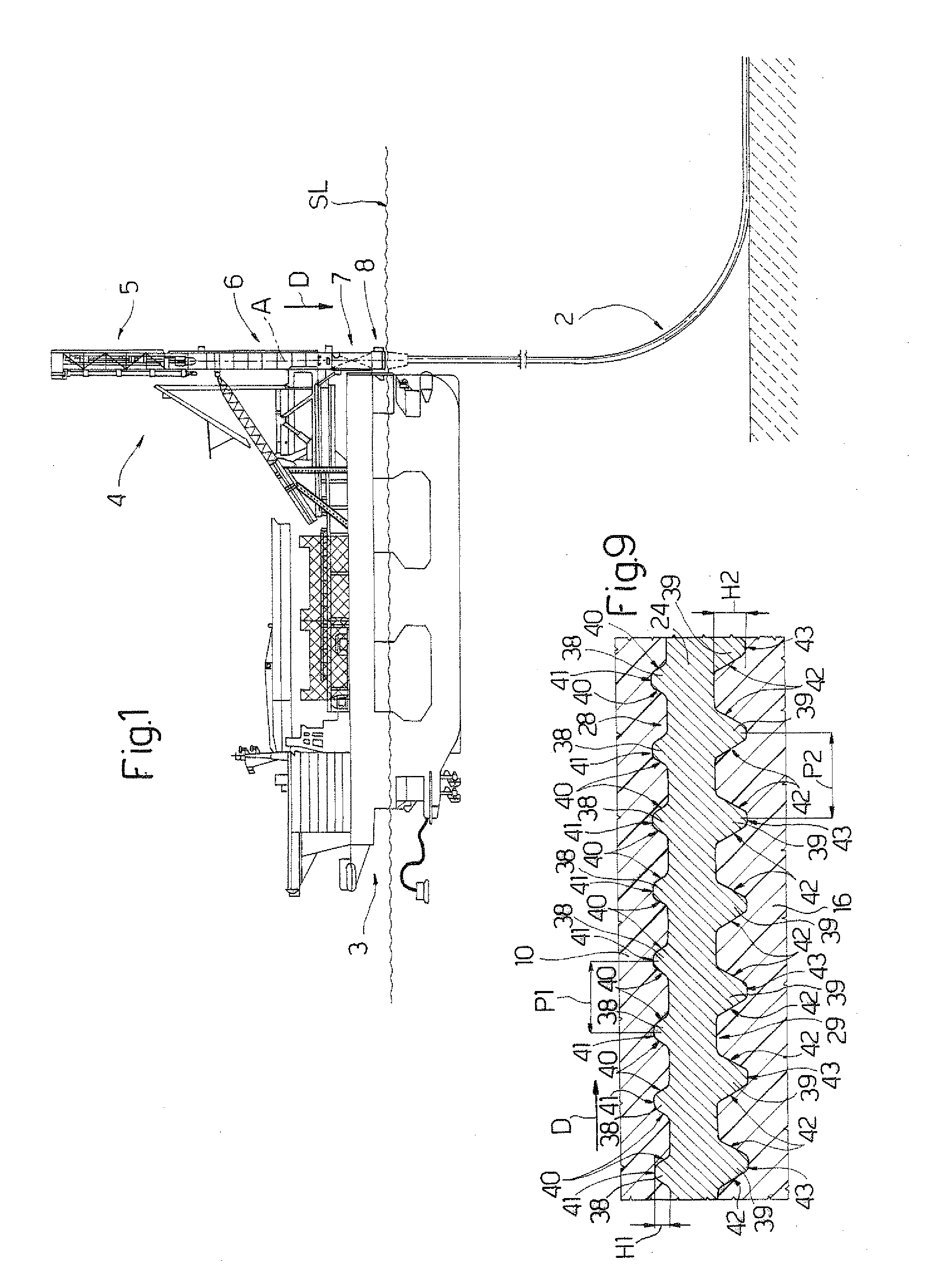
[0037]Number 1 in FIG. 1 indicates a laying vessel for constructing and laying in the sea (SL indicates sea level) an underwater pipeline 2 comprising a number of connected pipes (not shown). Laying vessel 1 is a particular type of laying vessel to which the present invention can be applied.

[0038]Laying vessel 1 comprises a semisubmersible ship 3; and a laying tower 4 extending in a direction D, hinged to semisubmersible ship 3, and designed for J laying. Though shown in an upright position, laying tower 4 may be tilted as much as 30° to the vertical when laying pipeline 2.

[0039]Laying tower 4 comprises a top portion 5 where pipeline 2 is assembled; an intermediate portion 6 housing a crawler tensioner not shown in the drawings; and a bottom portion 7 housing a gripping device 8.

The Underwater Pipeline

[0040]With reference to FIG. 2, pipeline 2 extends along an axis A parallel to laying direction D, and comprises a metal cylinder 9, and a protective covering 10 surro...


PUM


Abstract

A gripping device, for gripping underwater pipelines at the laying stage, has jaws that are pressed onto a pipeline extending along an axis substantially parallel to a laying direction, and have respective friction pads that are brought cyclically into contact with the outer face of the pipeline; and auxiliary gripping tools, which have panels for covering respective friction pads, and are selectively connectable to the jaws to increase grip between the jaws and the pipeline.

Description

TECHNICAL FIELD[0001]The present invention relates to a gripping device for gripping an underwater pipeline at the laying stage.[0002]More specifically, the present invention relates to a gripping device comprising jaws, which are pressed onto a pipeline extending along an axis substantially parallel to the laying direction; and each jaw comprises a friction pad that is brought cyclically into contact with the outer face of the pipeline.BACKGROUND ART[0003]An underwater pipeline is normally assembled on board a laying vessel, from which it is laid directly as it is assembled. The pipeline itself comprises a number of pipes joined to total lengths of hundreds of kilometers. The pipes are of normally 12-metre standard length, and relatively large diameters ranging between 0.2 and 1.5 metres, and each comprise a steel cylinder, and a coating of polymer material to protect the steel cylinder from corrosion and heat loss.[0004]The pipes are joined at on-land installations into multiple-s...

Claims


Application Information

Patent Timeline
Patent Type & Authority Applications(United States)
IPC IPC(8): B66C1/62B66C1/44B66C1/42
CPCF16L1/19F16L1/235F16L1/23F16L1/207
Inventor BAYLOT, MICHELBOUTIN, NICOLAS
Owner SAIPEM SPA
Learn More