Zoom lens system, imaging device and camera

a zoom lens and imaging device technology, applied in the field of zoom lens systems, can solve problems such as not meeting the requirements of digital cameras, and achieve the effects of high optical performance, rapid focusing, and high zooming ratio

Active Publication Date: 2011-10-27
PANASONIC CORP
View PDF6 Cites 33 Cited by
  • Summary
  • Abstract
  • Description
  • Claims
  • Application Information

AI Technical Summary

Benefits of technology

[0014]An object of the present invention is to provide: a zoom lens system which is compact but has a wide view angle at a wide-angle limit and a high zooming ratio, and still is able to perform rapid focusing and has high optical performance particularly in a close-object in-focus condition; an imaging device employing the zoom lens system; and a thin and compact camera employing the imaging device.
[0056]According to the present invention, it is possible to provide: a zoom lens system which is compact but has a wide view angle at a wide-angle limit and a high zooming ratio, and still is able to perform rapid focusing and has high optical performance particularly in a close-object in-focus condition; an imaging device employing the zoom lens system; and a thin and compact camera employing the imaging device.

Problems solved by technology

However, these conventional zoom lenses and imaging optical system are not sufficient in the focusing speed and the optical performance in the close-object in-focus condition, and therefore, do not meet the requirements for digital cameras in recent years.

Method used


Image

  • Zoom lens system, imaging device and camera
  • Zoom lens system, imaging device and camera
  • Zoom lens system, imaging device and camera

Examples


embodiments 1 to 6

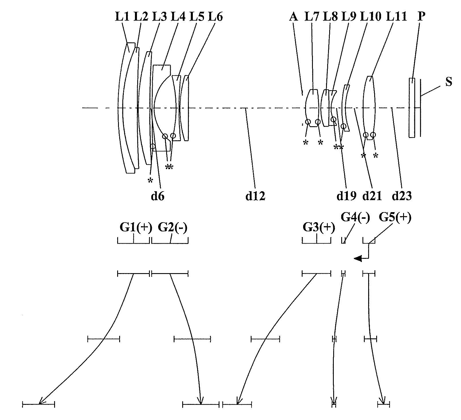
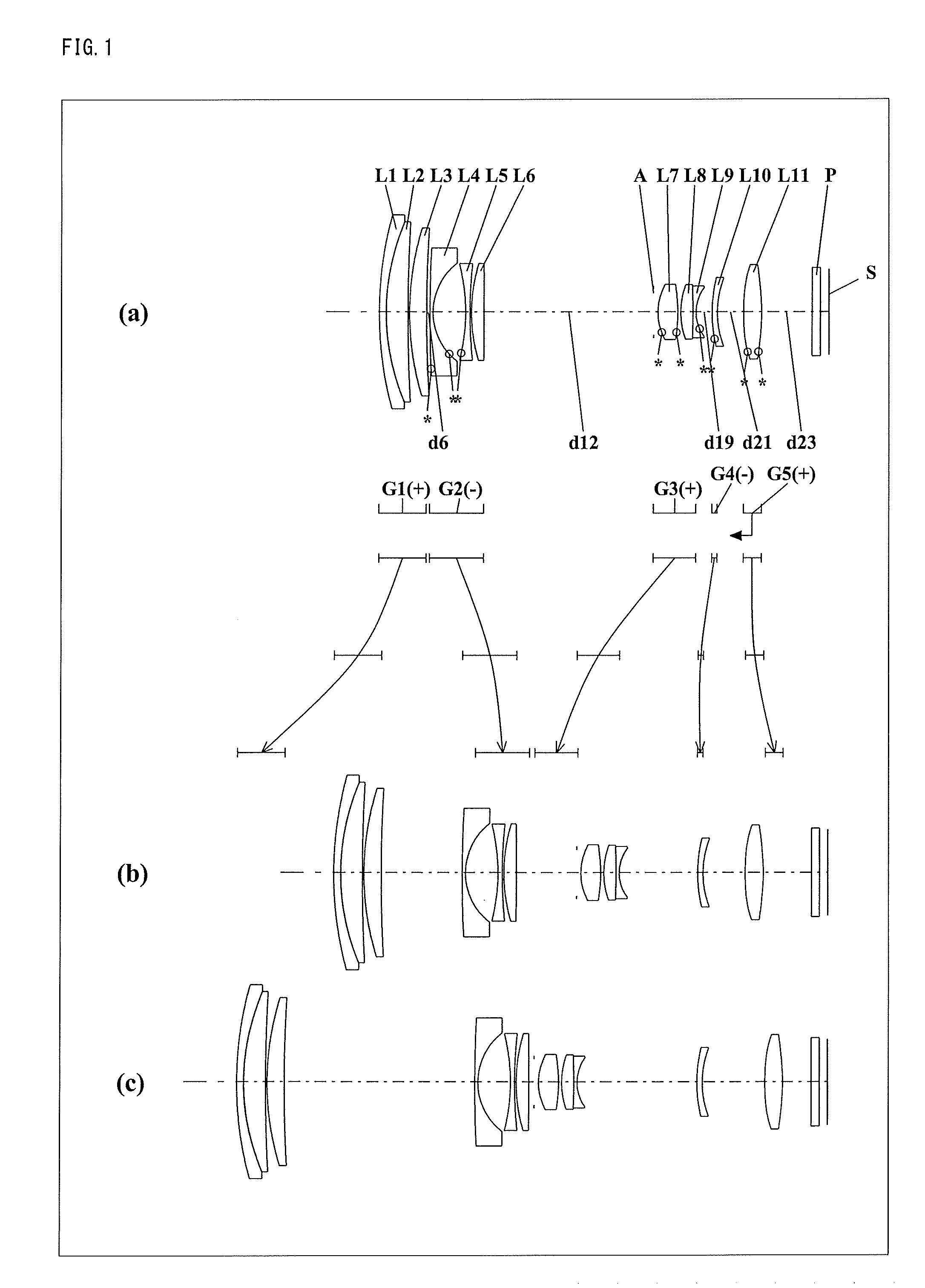
[0077]FIGS. 1, 4, 7, 10, 13, and 16 are lens arrangement diagrams of zoom lens systems according to Embodiments 1 to 6, respectively.

[0078]Each of FIGS. 1, 4, 7, 10, 13, and 16 shows a zoom lens system in an infinity in-focus condition. In each Fig., part (a) shows a lens configuration at a wide-angle limit (in the minimum focal length condition: focal length fW), part (b) shows a lens configuration at a middle position (in an intermediate focal length condition: focal length fM=√(fW*fT)), and part (c) shows a lens configuration at a telephoto limit (in the maximum focal length condition: focal length fT). Further, in each Fig., an arrow of straight or curved line provided between part (a) and part (b) indicates the movement of each lens unit from a wide-angle limit through a middle position to a telephoto limit. Moreover, in each Fig., an arrow imparted to a lens unit indicates focusing from an infinity in-focus condition to a close-object in-focus condition. That is, the arrow ind...

embodiment 7

[0189]FIG. 19 is a schematic construction diagram of a digital still camera according to Embodiment 7. In FIG. 19, the digital still camera comprises: an imaging device having a zoom lens system 1 and an image sensor 2 composed of a CCD; a liquid crystal display monitor 3; and a body 4. The employed zoom lens system 1 is a zoom lens system according to Embodiment 1. In FIG. 19, the zoom lens system 1 comprises a first lens unit G1, a second lens unit G2, an aperture diaphragm A, a third lens unit G3, a fourth lens unit G4 and a fifth lens unit G5. In the body 4, the zoom lens system 1 is arranged on the front side, while the image sensor 2 is arranged on the rear side of the zoom lens system 1. On the rear side of the body 4, the liquid crystal display monitor 3 is arranged, while an optical image of a photographic object generated by the zoom lens system 1 is formed on an image surface S.

[0190]The lens barrel comprises a main barrel 5, a moving barrel 6 and a cylindrical cam 7. Whe...

example 1 0.09

8 mm

Example 2 0.099 mm


PUM


Abstract

A zoom lens system comprising a first lens unit having positive optical power, a second lens unit having negative optical power, a third lens unit having positive optical power, a fourth lens unit having negative optical power, and a fifth lens unit having positive optical power, wherein the third lens unit includes at least one lens element having positive optical power and at least one lens element having negative optical power, at least the first to third lens units are moved along an optical axis in zooming so that air spaces between the respective lens units vary, thereby performing magnification change, a lens unit positioned on the image side relative to an aperture diaphragm is moved along the optical axis in focusing, and the conditions: 4.0<D / Ir<5.3 and Z=fT / fW≧9.0 (D: a total of optical axial thicknesses of respective lens units, Ir=fT×tan (ωT), ωT: a half view angle at a telephoto limit, fT and fW: focal lengths of the entire system at a telephoto limit and at a wide-angle limit) are satisfied; an imaging device; and a camera are provided.

Description

CROSS-REFERENCE TO RELATED APPLICATION[0001]This application is based on application No. 2010-102640 filed in Japan on Apr. 27, 2010, the contents of which are hereby incorporated by reference.BACKGROUND OF THE INVENTION[0002]1. Field of the Invention[0003]The present invention relates to a zoom lens system, an imaging device, and a camera. In particular, the present invention relates to: a zoom lens system which is compact but has a wide view angle at a wide-angle limit and a high zooming ratio, and still is able to perform rapid focusing and has high optical performance particularly in a close-object in-focus condition; an imaging device employing the zoom lens system; and a thin and compact camera employing the imaging device.[0004]2. Description of the Background Art[0005]Size reduction and high performance, particularly, a high zooming ratio, are strongly required of cameras having image sensors performing photoelectric conversion, such as digital still cameras and digital vide...

Claims


Application Information

Patent Timeline
Patent Type & Authority Applications(United States)
IPC IPC(8): H04N5/232G02B15/14
CPCG02B15/173G02B15/145121
Inventor TOUCHI, YASUNORIBITO, TAKAKAZUYAMAGUCHI, SHINJI
Owner PANASONIC CORP
Why Eureka
Try Eureka