Control circuit for primary side control of switching power supply

a control circuit and power supply technology, applied in the field of switch mode power supply, can solve the problems of high cost, easy variation, and unsatisfactory conventional techniques for controlling a switch mode power supply

Active Publication Date: 2011-10-27
BCD SHANGHAI MICRO ELECTRONICS CO LTD
View PDF19 Cites 73 Cited by
  • Summary
  • Abstract
  • Description
  • Claims
  • Application Information

AI Technical Summary

Benefits of technology

[0009]The inventors of the present invention have recognized that, in a single switching cycle, the time integral of the absolute value of the negative voltage pulse across the auxiliary winding (when power switch transistor is turned on) is equal to the time integral of the absolute value of the positive voltage pulse across the auxiliary winding (when power switch transistor is turned o

Problems solved by technology

As described above, conventional techniques for controlling a switch mode power supply are often unsatisfactory.
For example, the fixed delay sampling method may work for a specific configuration of output load, but would be costly if it needs to be

Method used


Image

  • Control circuit for primary side control of switching power supply
  • Control circuit for primary side control of switching power supply
  • Control circuit for primary side control of switching power supply

Examples


Embodiment Construction

[0030]Merely for illustration, some embodiments of the present invention are described below using examples of fly-back converters for AC / DC or DC / DC conversion. However, embodiments of the invention are not limited to such converters. For example, embodiments of the present invention can be applied to any converters in which quick adjustment to output load conditions is desired.

[0031]The description below is presented with reference to a series of drawing figures enumerated above. These diagrams are merely examples, and should not unduly limit the scope of the claims herein. In connection with the various aspects illustrated and described, one of ordinary skill in the art would recognize other variations, modifications, and alternatives.

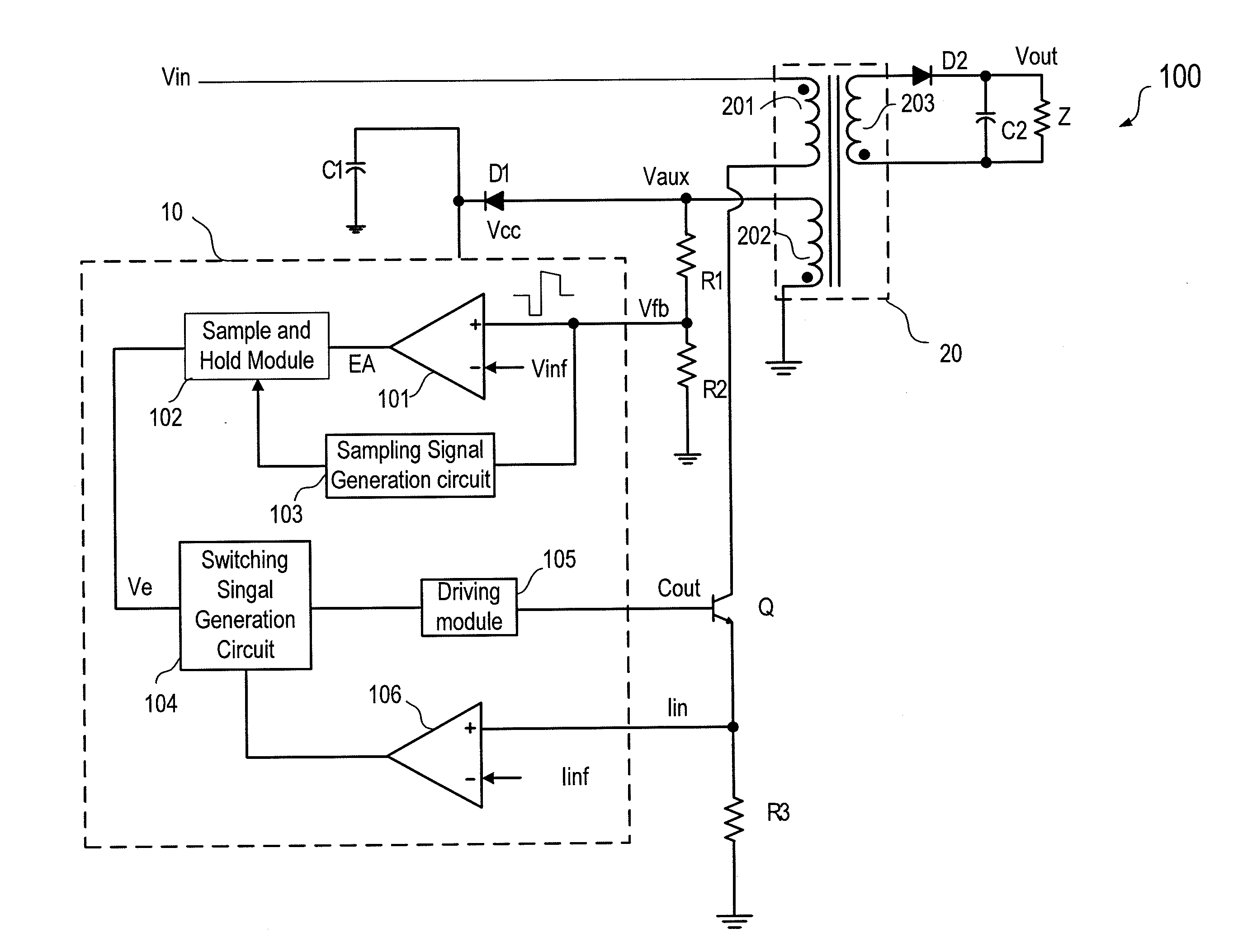
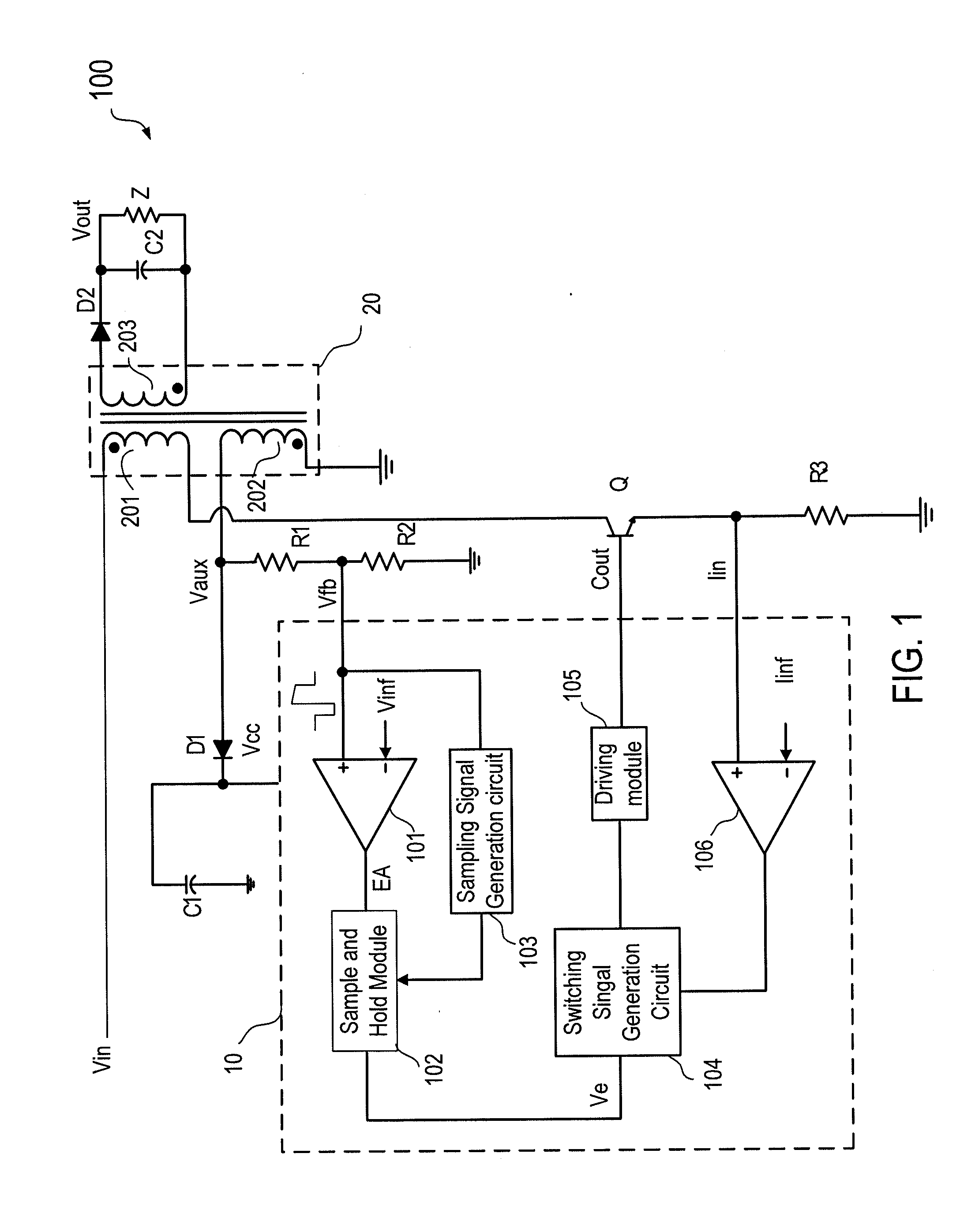
[0032]FIG. 1 is a simplified block diagram illustrating a fly back converter 100 according to an embodiment of the present invention. As shown, flyback converter 100 includes a control circuit 10, a transformer 20, a power switch Q, a first resistor...


PUM


Abstract

A switched mode power supply (SMPS) includes a transformer with a primary winding, a secondary winding, an auxiliary winding, and a power switch coupled to the primary winding. During one switching cycle, the auxiliary winding provides a feedback signal which includes a first voltage pulse that is induced after the power switch is turned on and a second voltage pulse that is induced after the power switch is turned off. A control circuit includes a circuit for generating a sampling signal for sampling the second voltage pulse in a switching cycle at a time that is determined based on the first voltage pulse in the same switching cycle. A sample-and-hold circuit is configured for sampling and storing the second voltage pulse in response to the sampling signal. A switching signal generating circuit is configured to generate a switching signal for controlling the power switch based on an output of the sample-and-hold circuit.

Description

CROSS-REFERENCES TO RELATED APPLICATIONS[0001]This application claims priority to Chinese Patent Application No. 201010157899, filed Apr. 27, 2010, which is commonly owned and incorporated by reference in its entirety herein for all purposes.BACKGROUND OF THE INVENTION[0002]The present invention relates generally to the field of switch mode power supply (SMPS). More particularly, embodiments of the present invention relate to circuits and methods for primary side control of a flyback switching power supply.[0003]Switching power supplies have become increasingly important in today's technologies, from personal computers to portable electronic devices. Compared with traditional linear power supplies, switching mode power supplies have advantages such as small size, good stability, high efficiency, and low cost, etc. As a result, switching power supplies are commonly used in low-cost, low power applications. Among the many types of switching power supplies, flyback switching power supp...

Claims


Application Information

Patent Timeline
IPC IPC(8): H02M3/335
CPCH02M3/33507
Inventor ZONG, QIANGZHU, HUIZHENZHAO, PINGANZHU, YAJIANG
Owner BCD SHANGHAI MICRO ELECTRONICS CO LTD
Why Eureka
Try Eureka