Dental matrix

a technology of dental matrix and interproximal placement, applied in the field of dental matrix, can solve the problems of difficult interproximal placement of dental matrix, loss of contact point with adjacent teeth, and special difficulty, and achieve the effect of effective and efficient insertion

Inactive Publication Date: 2011-10-27
GALLER JEFFREY
View PDF22 Cites 7 Cited by
  • Summary
  • Abstract
  • Description
  • Claims
  • Application Information

AI Technical Summary

Benefits of technology

[0013]In view of the deficiencies and drawbacks in the prior art, it is a primary object of the present invention to provide a dental matrix that is adapted to effectively and efficiently be inserted between adjacent teeth so that a cavity may be filled interproximally and to provide a proper contact point with the adjacent tooth.
[0015]Yet another object of the present invention is to provide a dental matrix that is adapted for a dentist to maintain visibility and accessibility to fill a cavity.
[0016]Yet another object of the present invention is to provide a dental matrix that is adapted to fit between tight contact points without the use of a separating ring or wedge during preparation of a cavity.

Problems solved by technology

However, if a tooth experiences decay or otherwise experiences damage, its contact point with the adjacent tooth may be lost.
A common problem in placing a matrix interproximally is that the tooth to be filled will often be in very tight contact with the adjacent tooth, and therefore it becomes difficult to place the matrix interproximally.
This difficulty is especially pronounced when using sectional matrix strips that merely cover one interproximal wall of the affected tooth, as opposed to circumferential matrix bands that fit over and around the entire tooth somewhat more easily.
However, cutting away healthy, irreplaceable tooth structure is undesirable since it is not minimally invasive.
The problem with this technique, however, is that the pre-operative presence of the ring or wedge limits visibility and accessibility for the dentist.
Despite its ostensible utility, this matrix suffers from a number of deficiencies.
For example, the matrix does not effectively loosen the tight space between the adjacent teeth for entry of the matrix since the depth of the matrix is comprised of both the sheet metal and wire ligature.
In practice, such a matrix is actually more difficult to pass through the space between the teeth since the sheet metal and wire ligature must pass through the space at once.
However, this matrix is difficult to place interproximally and is used in conjunction with a separating ring during the preparation of the cavity.
The prior art does not provide for a dental matrix which is easily inserted interproximally.
Current matrices are difficult to insert between tight contact points.
That is, prior art applications, including those referenced above, have in general provided a matrix that is bulky and difficult to insert without either cutting away additional, irreplaceable tooth structure or by first utilizing a separating ring or wedge in order to facilitate inserting the matrix between the adjacent teeth.

Method used


Image

  • Dental matrix
  • Dental matrix
  • Dental matrix

Examples


Embodiment Construction

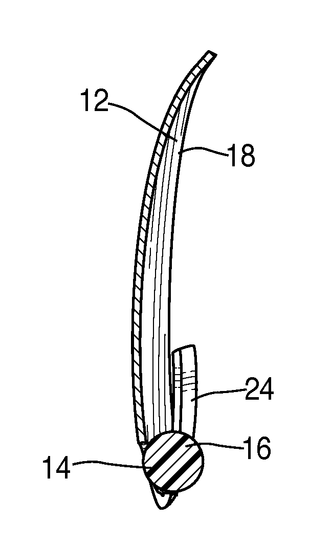
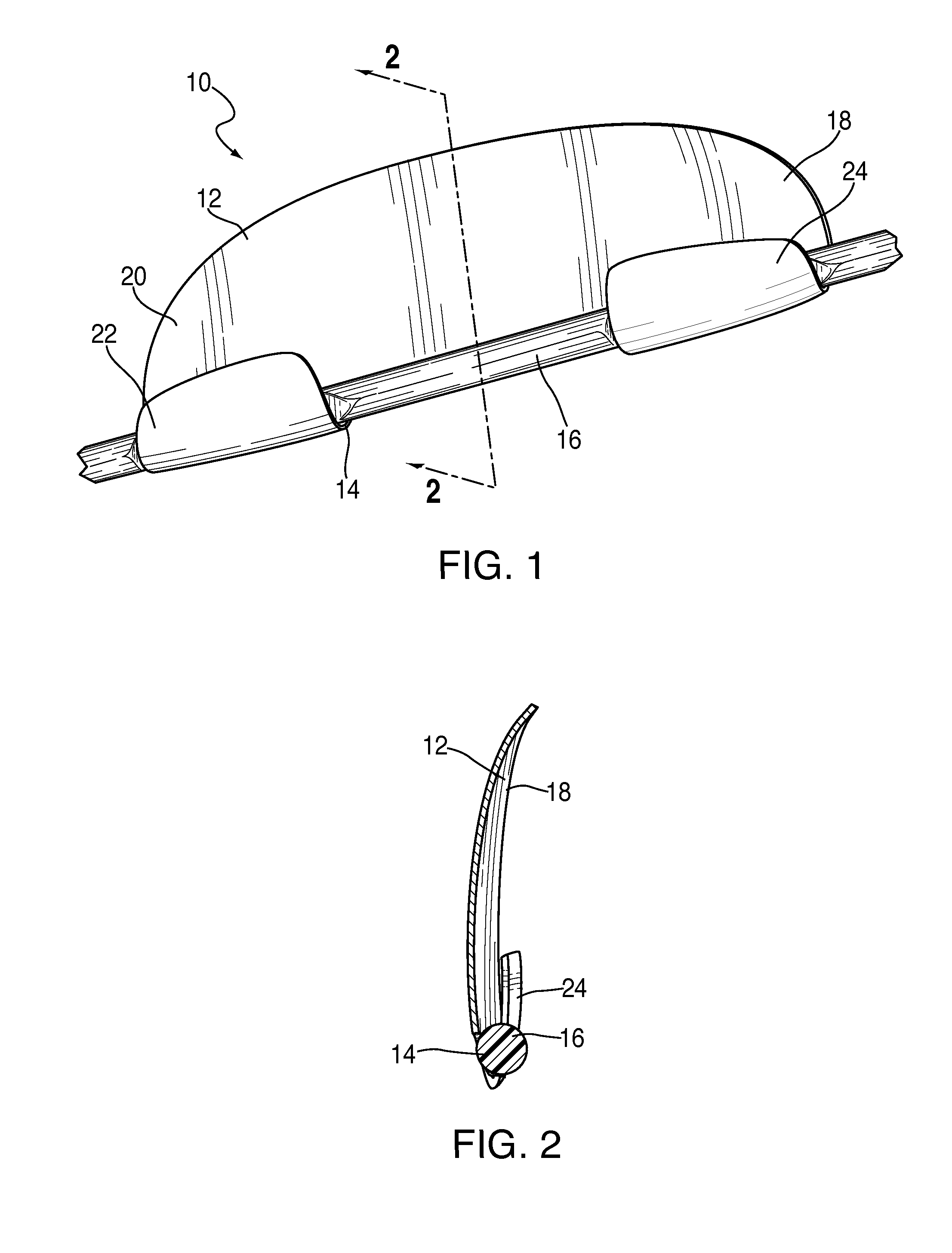
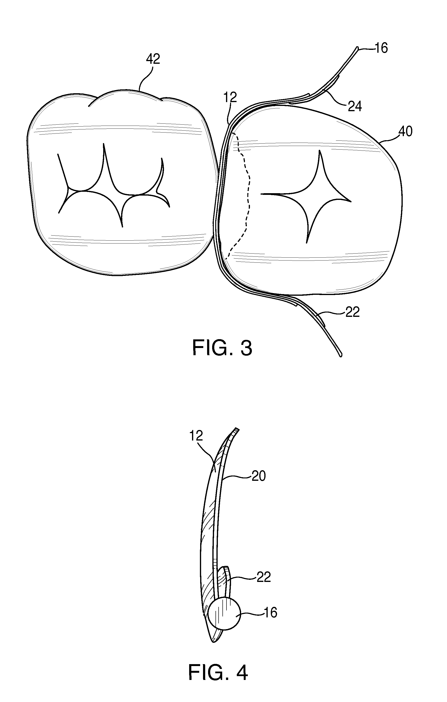
[0029]With reference to FIGS. 1 through 4, there is shown a preferred embodiment of a dental matrix 10 of the present invention. Generally, the dental matrix 10 has a band 12 with an edge 14 for placement toward the gingival margin of the tooth 40 to be restored, and a strip 16 attached to and extending along edge 14. The band 12 is preferably formed of stainless spring steel or any other appropriate metallic, plastic or other flexible and resilient material. Stainless spring steel provides the band 12 with flexibility so that it can be molded around a tooth into a desired position. Preferably, the band 12 is a sectional band rather than a circumferential band.

[0030]The strip 16 is preferably formed of dental floss comprised of nylon filaments or plastic ribbon. Preferably, polytertafluoroethylene (PTFE) ribbon sold under the brand name Teflon® may be utilized, but other materials having an ease-of-insertion property comparable to that of dental floss such as polyethylene fibers, po...


PUM


Abstract

A dental matrix comprising a band with an edge for placement toward the gingival margin of a tooth to be restored, and a strip of dental floss attached to and extending along an edge of the band. In the preferred embodiment, buccal and lingual extensions are located beyond a central portion of the band along the edge. The extensions are folded over the strip of dental floss so as to secure the strip of dental floss to the edge.

Description

RELATED APPLICATION[0001]This application claims priority to provisional application Ser. No. 61 / 326,782 filed on Apr. 22, 2010 and incorporated herein by reference.FIELD OF INVENTION[0002]The present invention relates generally to a dental matrix. More specifically, the invention involves an improved dental matrix for use in conjunction with fillings located at the interproximal areas between adjacent teeth.BACKGROUND OF THE INVENTION[0003]A number of dental matrices for use in connection with filling cavities have been available for some time. Some of these matrices are specifically designed for fillings located in interproximal areas between adjacent teeth.[0004]Normally, adjacent healthy teeth are in proximal contact with each other at a contact point. However, if a tooth experiences decay or otherwise experiences damage, its contact point with the adjacent tooth may be lost. During restoration of the tooth, therefore, it is important for a proper contact point with the adjacent...

Claims


Application Information

Patent Timeline
Patent Type & Authority Applications(United States)
IPC IPC(8): A61C5/04
CPCA61C5/125A61C5/85
Inventor GALLER, JEFFREY
Owner GALLER JEFFREY
Why Eureka
Try Eureka