Conveyor system and method of conveying elements

a conveying system and conveying system technology, applied in the direction of mechanical conveyors, conveyors, packaging, etc., can solve the problems of inability to use the steel base as a datum for such applications, the steel belt of the conveying conveyor wears and must be frequently replaced, and the inability to accurately locate the point, so as to avoid damage to the conveying conveyor and the conveying elements, the effect of avoiding wear or damage to the pall

Inactive Publication Date: 2006-12-21
DURR SYST INC
View PDF19 Cites 28 Cited by
  • Summary
  • Abstract
  • Description
  • Claims
  • Application Information

AI Technical Summary

Benefits of technology

[0006] The conveyor system of this invention is rugged, reliable and operates in a unique way to avoid damage to the conveyor and the elements conveyed by the conveyor system. The conveyor system of this invention may be utilized to convey heavy parts or components as required by many industries. Where the parts or components are conveyed on pallets, the conveyor system of this invention also avoids wear or damage to the pallets. As set forth above, many industries now use expensive pallets to convey parts or components having one or a plurality of datums and the parts or components are mounted on the pallets for secondary operations, such as assembly of components or welding, which requires accurate location of points on the parts conveyed by robots or the like. The conveyor system of this invention is also flexible and may be utilized to stop or hold the parts at any predetermined locations for timing reasons or secondary operations and convey the parts or components in any direction as required by the operations of the facility. For ease of this description, the parts, components or assemblies conveyed by the conveyor system will be referred to as “elements” and may be any part, component or assembly which is conveyed by a conveyor system with or without a pallet.

Problems solved by technology

As set forth above, many industries now use expensive pallets to convey parts or components having one or a plurality of datums and the parts or components are mounted on the pallets for secondary operations, such as assembly of components or welding, which requires accurate location of points on the parts conveyed by robots or the like.
Nevertheless, the steel belt of the conveyor wears and must be frequently replaced.
Further, the conveyor includes retractable stops which stop the pallet as required for the facility and the pallet is worn or damaged by the steel conveyor belt and the sudden stops, damaging the steel base of the pallet requiring replacement and making it impractical to use the steel base as a datum for such applications.
Finally, the noise level generated by the conveyor system requires the use of noise reduction protective head gear.

Method used


Image

  • Conveyor system and method of conveying elements
  • Conveyor system and method of conveying elements
  • Conveyor system and method of conveying elements

Examples


Embodiment Construction

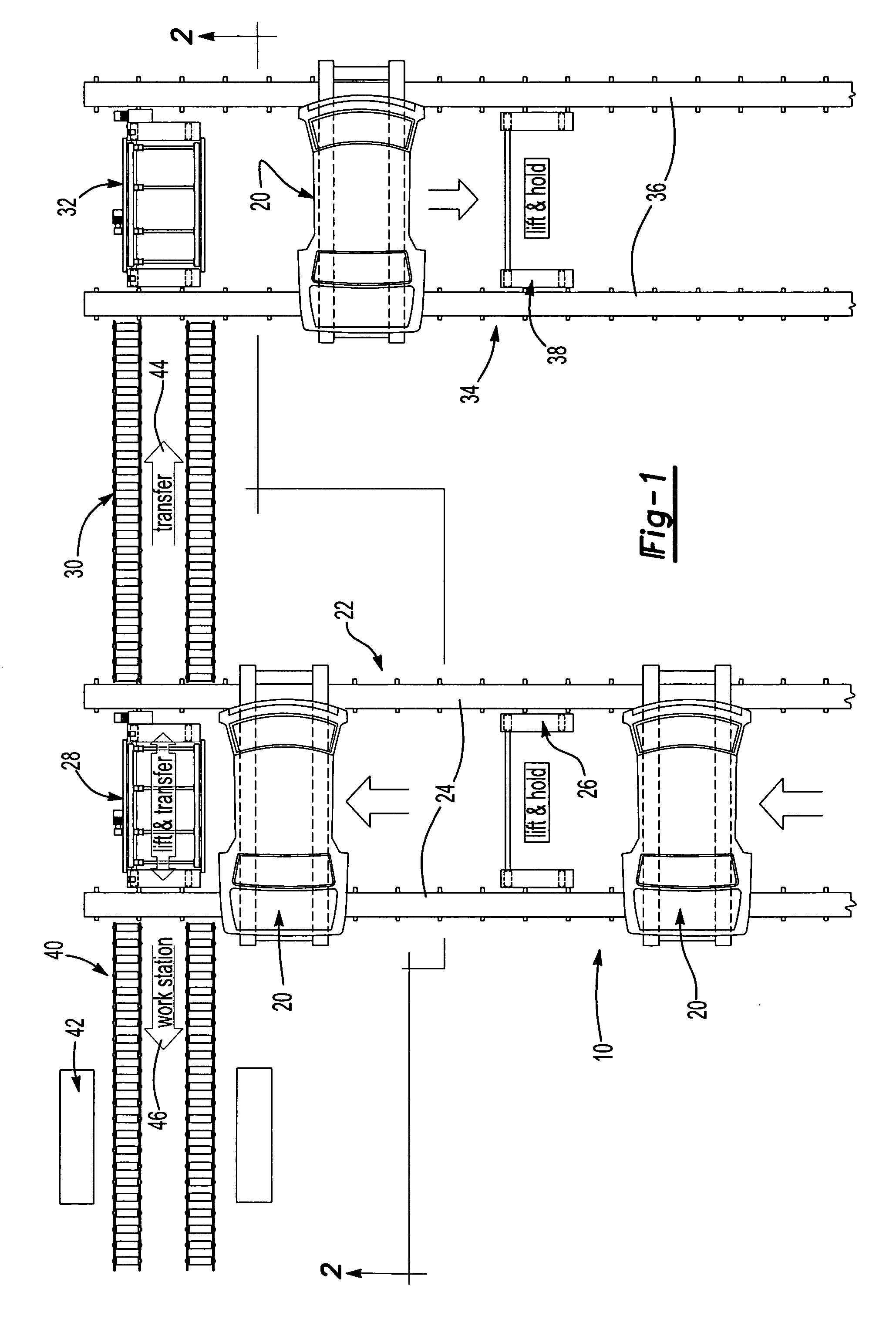
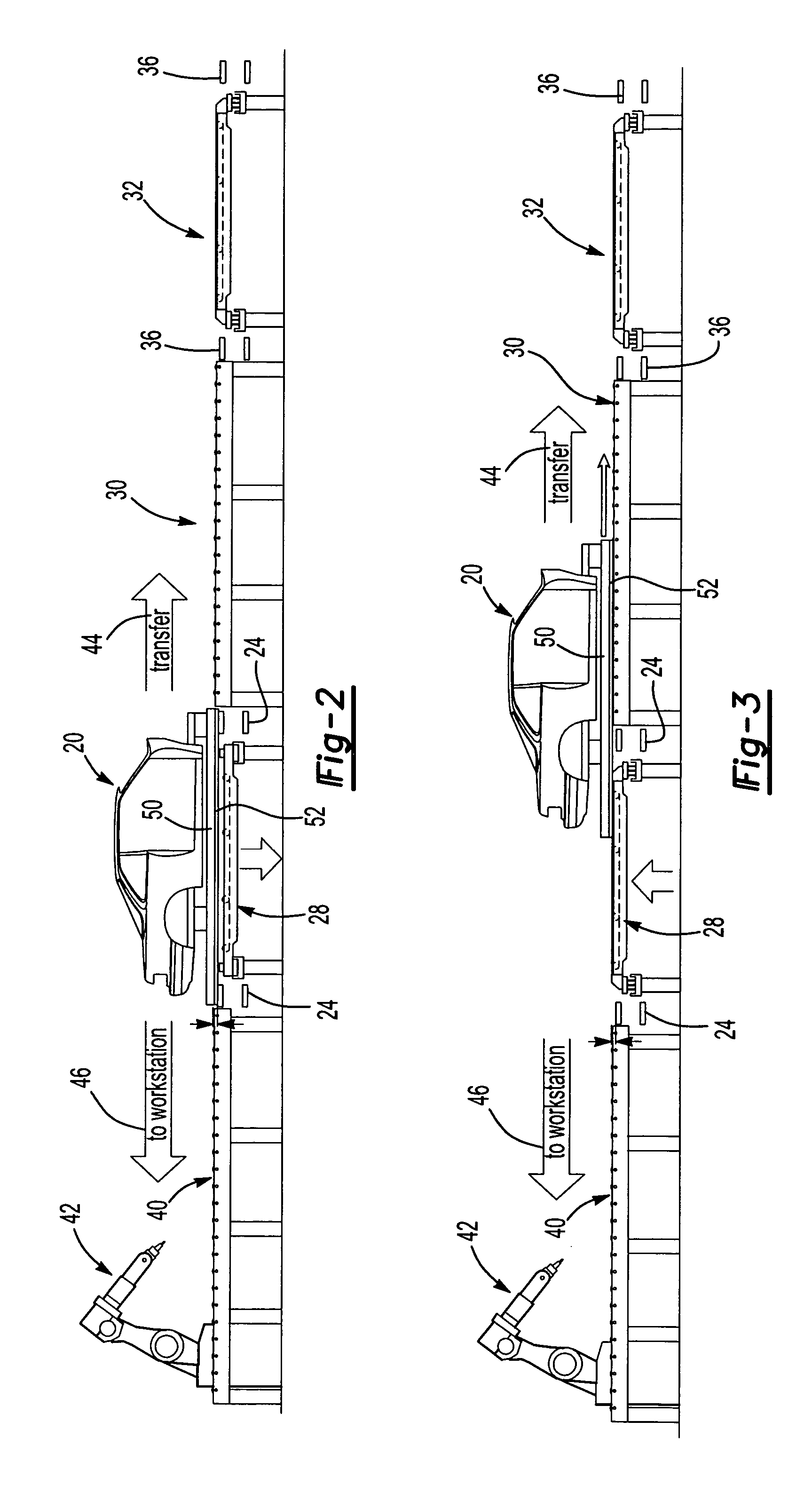
[0025] As set forth above, the conveyor system 10 and method of this invention may be utilized to convey elements of any type in a manufacturing or assembly facility, but is particularly useful for transferring heavy elements in a mass production facility, such as vehicle bodies 20 in an automotive manufacturing, assembly or paint facility. As will be understood, however, the conveyor system and method of this invention is not limited to the elements conveyed and the elements may be conveyed with the conveyor system and method of this invention without pallets.

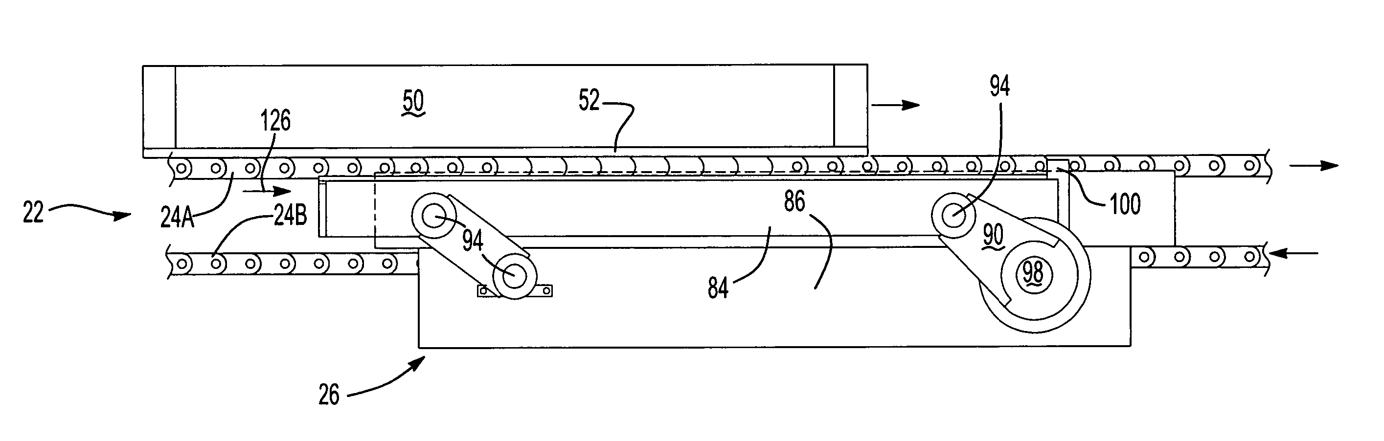
[0026] The embodiment of the conveyor system 10 illustrated in FIG. 1 for transferring or conveying vehicle bodies 20 includes a first conveyor 22 preferably including spaced continuous moving belts 24 as described more fully hereinbelow. The disclosed embodiment of the conveyor system 10 further includes one or a plurality of lift and hold tables 26, more accurately referred to as lift, hold and return tables which, in a pre...


PUM


Abstract

The method of conveying elements on a conveyor system of this invention includes conveying an element on a first continuously moving conveyor in a first direction at a first height, then lifting the element from the first conveyor upwardly to a second height and simultaneously moving the element in the first direction, reducing damage to the conveyor and the element. The element may be returned to the first conveyor by lowering the element and simultaneously accelerating the element to generally the velocity of the first conveyor or transferred to a second conveyor at the second height. The conveyor system of this invention includes spaced parallel plastic moving belts and the elements are conveyed on a pallet having a soft metal base. The lift tables include parallelogram lift and lowering linkages.

Description

FIELD OF THE INVENTION [0001] This invention relates to conveyor systems and methods of conveying articles or elements on a conveyor which extends the useful life of the conveyor and reduces damage to the elements conveyed by the conveyor, particularly including expensive pallets to convey heavy parts by many industries. The method and conveyor system of this invention may be utilized to convey large parts, such as vehicle bodies, through an automotive manufacturing plant, typically mounted on pallets to various locations in the manufacturing facility. BACKGROUND OF THE INVENTION [0002] Various industries now convey heavy parts or components mounted on expensive pallets, which may cost in excess of $20,000, on conveyor systems through an assembly or manufacturing plant for various operations, such as assembly, welding, painting and the like. As will be understood by those skilled in this art, such conveyor systems must be rugged, reliable and capable of stopping movement of the part...

Claims


Application Information

Patent Timeline
Patent Type & Authority Applications(United States)
IPC IPC(8): B65G47/24
CPCB62D65/18B65G2201/0294B65G47/53
Inventor HEINEMEIER, THOMASKARRER, PETER
Owner DURR SYST INC
Why Eureka
Try Eureka