Power factor correction controller and power supply apparatus using the same

a technology of power factor correction and controller, which is applied in the field of power conversion techniques, can solve the problems of high cost, large circuit area, and high cost of current pfc controller design, and achieve the effect of accurate prediction and high power factor correction

Inactive Publication Date: 2016-04-14
METAL INDS RES & DEV CENT
View PDF1 Cites 28 Cited by
  • Summary
  • Abstract
  • Description
  • Claims
  • Application Information

AI Technical Summary

Benefits of technology

[0007]The invention provides a power factor correction (PFC) controller and a power supply apparatus applying the same capable of accurately predicting a zero-current time point with auxiliary winding free, so as to achieve a boundary conduction mode (BCM) operation of high power factor correction.
[0024]To sum up, a PFC controller and a power supply apparatus applying the same are provided according to the embodiments of the invention. The PFC controller can accurately predict the zero-current time point by using information, such as the input voltage, the output voltage and the driving signal cycle according to the charge / discharge time characteristics of the capacitors, with auxiliary winding free, such that the power supply apparatus can be operated in the BCM to increase the power factor. Moreover, the embodiments of the invention further provide the current source adjustment mechanism and circuits for compensating device / characteristic / process drifts, and thereby, the zero-current time point can be predicted with more accuracy.

Problems solved by technology

In recent years, energy shortages have become more and more serious, and therefore, subjects with respect to green power industry has drawn more and more attention from people.
However, in order to perform zero-current detection, the current PFC controller designs requires bulky and costly auxiliary winding is required for providing information with respect to the output current and thereby detecting the zero-current time point.
However, the use of the auxiliary winding not only cost high and occupies a large circuit area, but also causes inaccuracy in the zero-current detection due to process drifts, which leads to excessive power loss and power factor reduction of the power supply apparatus.

Method used


Image

  • Power factor correction controller and power supply apparatus using the same
  • Power factor correction controller and power supply apparatus using the same
  • Power factor correction controller and power supply apparatus using the same

Examples


Embodiment Construction

[0033]In order to make the content of the invention clearer, the following embodiments are illustrated as examples that can be truly implemented by the invention. Wherever possible, the same reference numbers are used in the drawings and the description to refer to the same or like elements / parts / steps.

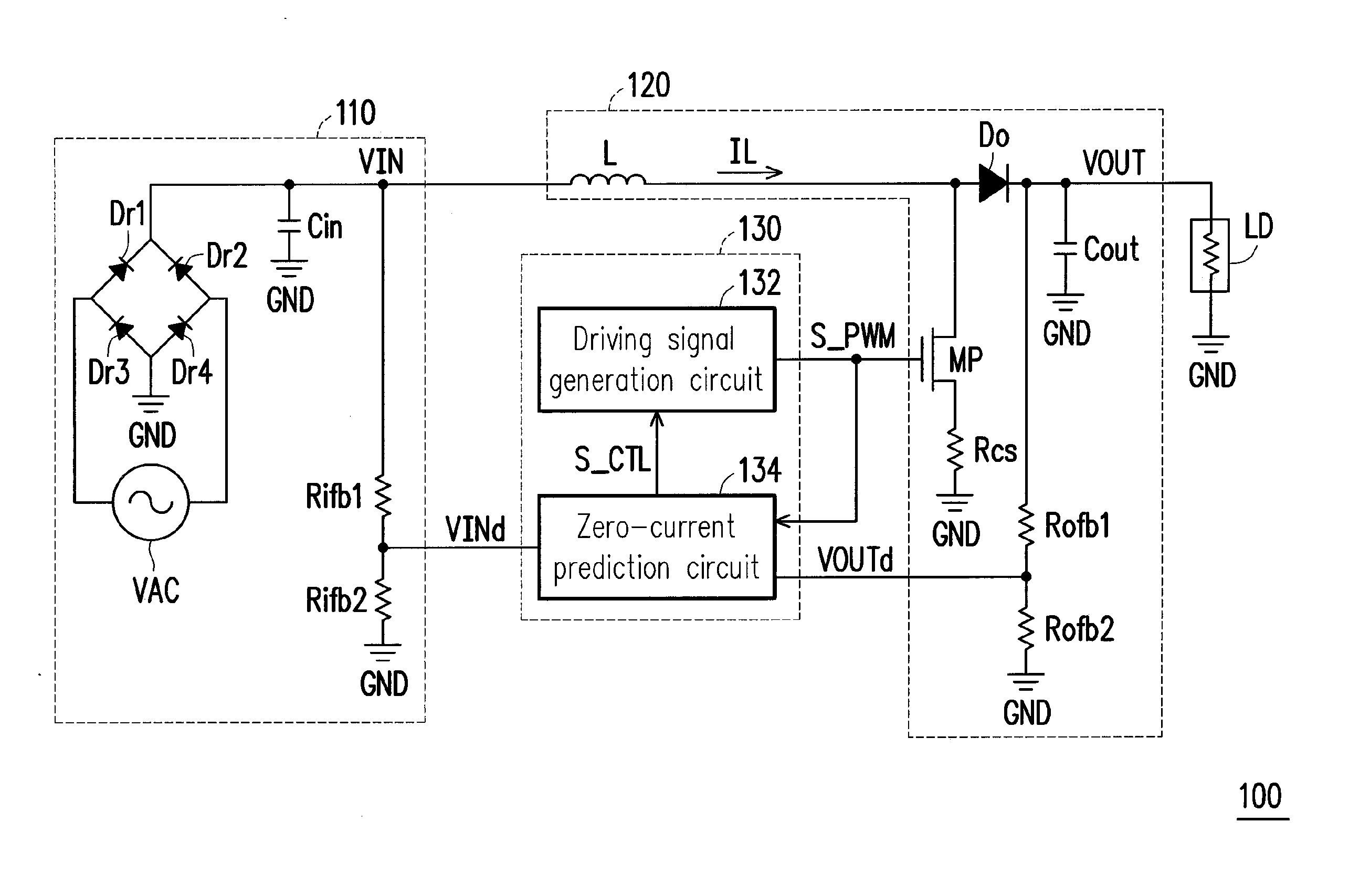
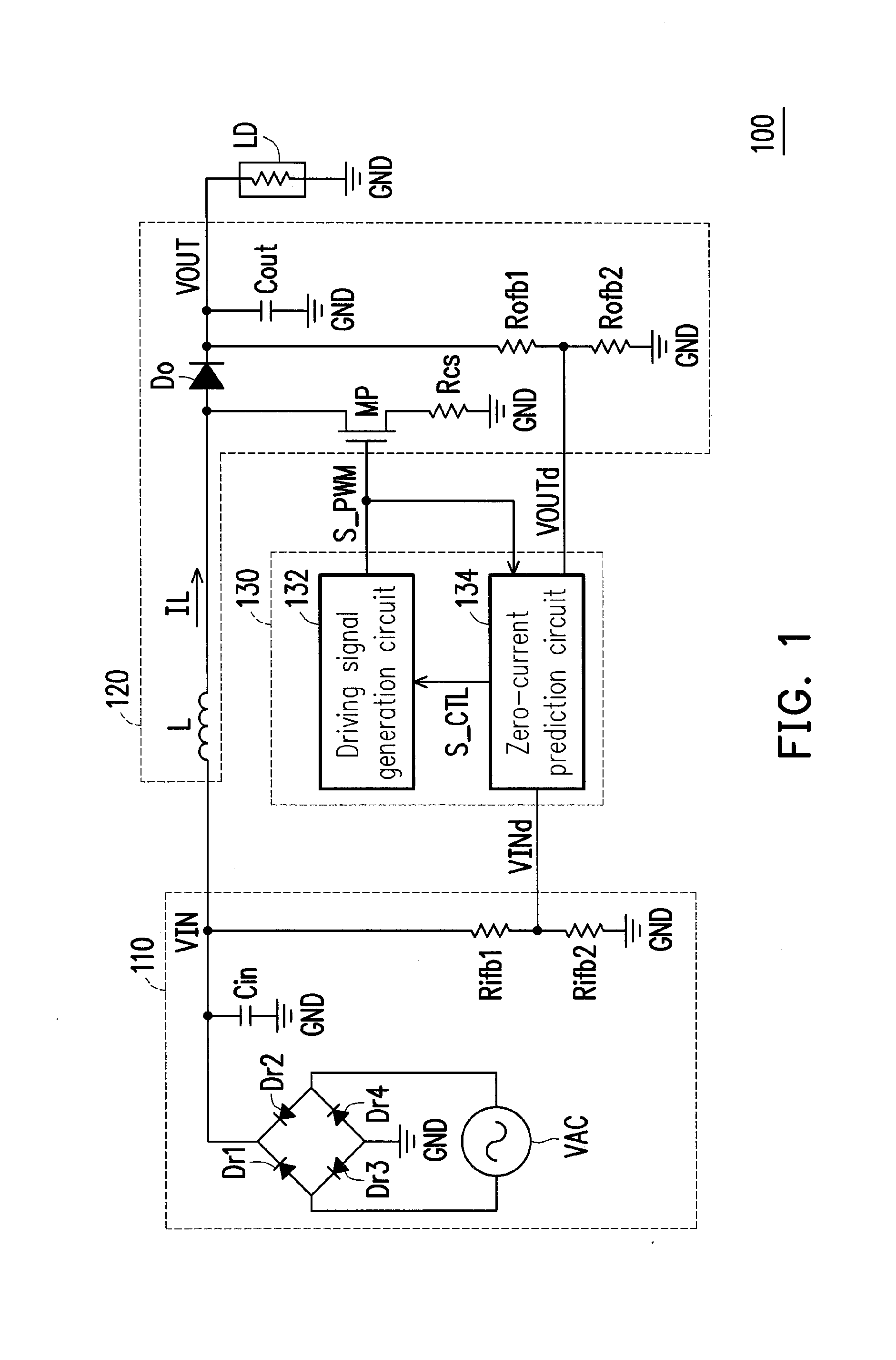
[0034]FIG. 1 is a schematic diagram of a power supply apparatus according to an embodiment of the invention. With reference to FIG. 1, a power supply apparatus 100 of the present embodiment includes an input-stage circuit 110, a power-stage circuit 120 and a power factor correction (PFC) controller 130. The input-stage circuit 110 may be configured to convert an AC power supply VAC into an input voltage VIN. The power-stage circuit 120 is coupled to the input-stage circuit 110. The power-stage circuit 120 charges / discharges a resonator component (e.g., an inductor L) according to the input voltage VIN by means of switching, so as to convert the input voltage VIN into an output voltage...


PUM


Abstract

A power factor correction (PFC) controller and a power supply apparatus using the same are provided. The PFC controller includes a driving signal generation circuit and a zero-current prediction circuit. The driving signal generation circuit generates a driving signal to drive a power switch according to a control signal, where the power switch is switched in response to the driving signal, so as to convert an input voltage into an output voltage. The zero-current prediction circuit is coupled to the driving signal generation circuit and performs a capacitance charge / discharge operation, and thus obtains a charge / discharge time characteristic related to a zero-current timing. The zero-current prediction circuit generates the control signal to control operation of the driving signal generation circuit according to the charge / discharge time characteristic.

Description

BACKGROUND[0001]1. Field of the Invention[0002]The invention is directed to a power conversion technique and more particularly, to a power factor correction (PFC) controller and a power supply apparatus applying the same.[0003]2. Description of Related Art[0004]In recent years, energy shortages have become more and more serious, and therefore, subjects with respect to green power industry has drawn more and more attention from people. Thus, how to design power supply apparatuses with high efficiency is a target that the industry has made efforts to achieve.[0005]In a power supply apparatus, a PFC controller is commonly used to control output of the power supply apparatus, such that the output current generated by the power supply apparatus and an input AC power supply can tend to have the same phase. Thereby, available real power can be optimally applied to achieve an effect of high power factor. Under the current technique, the power supply apparatus is generally operated in a boun...

Claims


Application Information

Patent Timeline
Patent Type & Authority Applications(United States)
IPC IPC(8): H02M1/42
CPCH02M1/4225Y02B70/10
Inventor CHEN, KE-HORNGLUO, HSIN-YULIU, WEN-JIUNMENG, CHE-HAOCHANG, CHIH-WEI
Owner METAL INDS RES & DEV CENT
Why Eureka
Try Eureka