Torsional vibration damper

Inactive Publication Date: 2011-10-27
SCHAEFFLER TECH AG & CO KG
View PDF2 Cites 11 Cited by
  • Summary
  • Abstract
  • Description
  • Claims
  • Application Information

AI Technical Summary

Benefits of technology

[0005]An object of the invention is a torsional

Problems solved by technology

The centrifugal forces occurring through rotation of the torsional vibration damper and deflection of the coil spring, cause an action of force

Method used


Image

  • Torsional vibration damper
  • Torsional vibration damper
  • Torsional vibration damper

Examples


Embodiment Construction

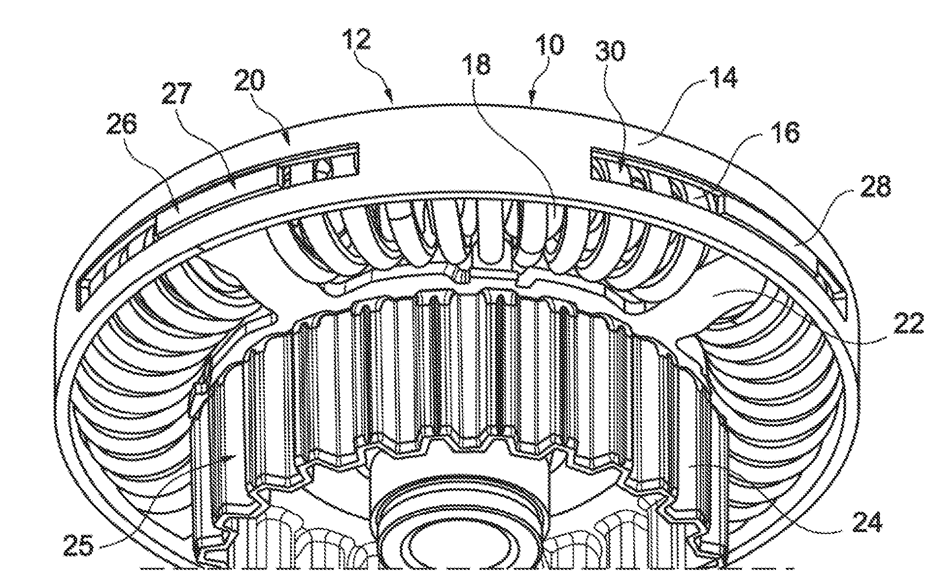
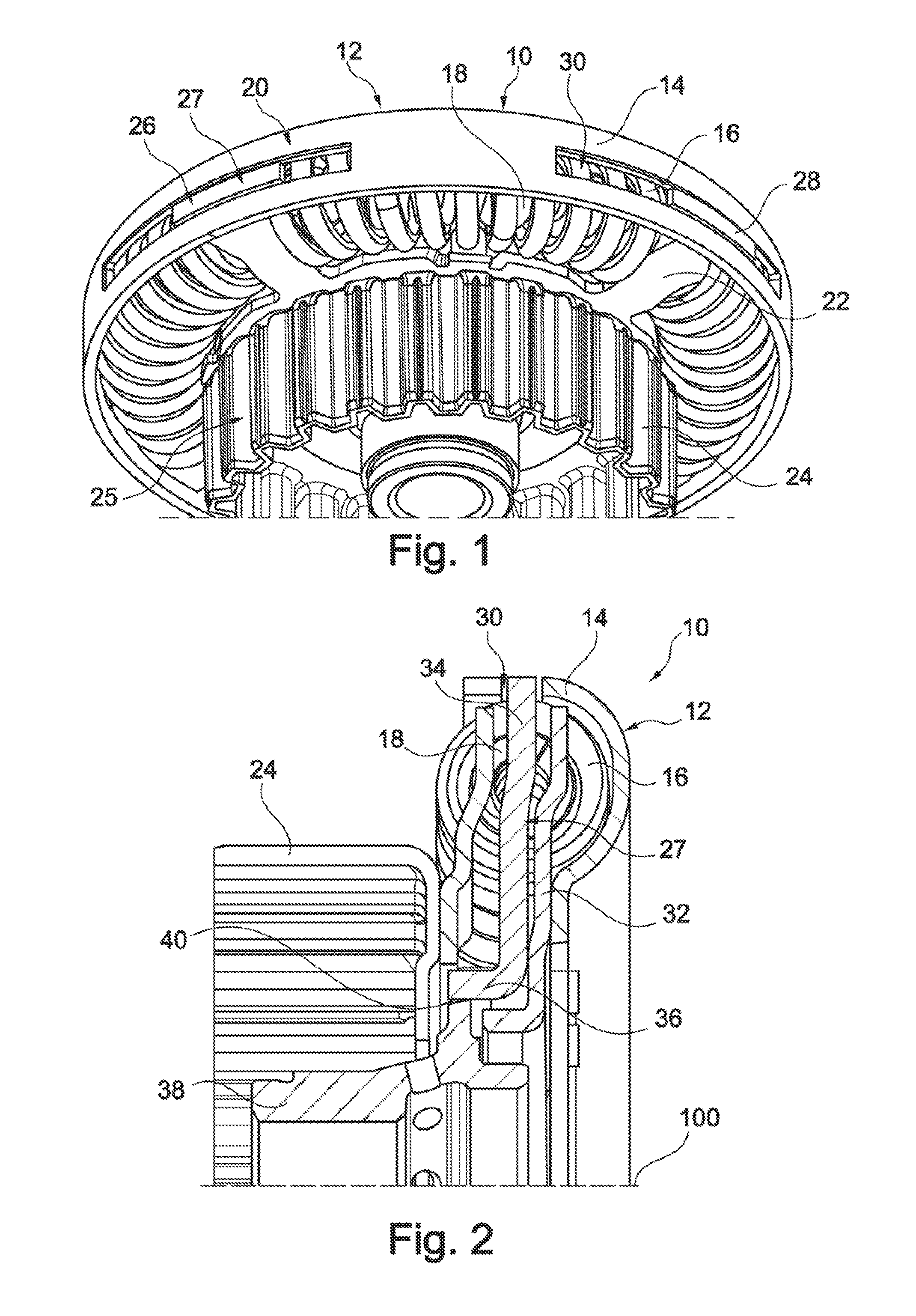
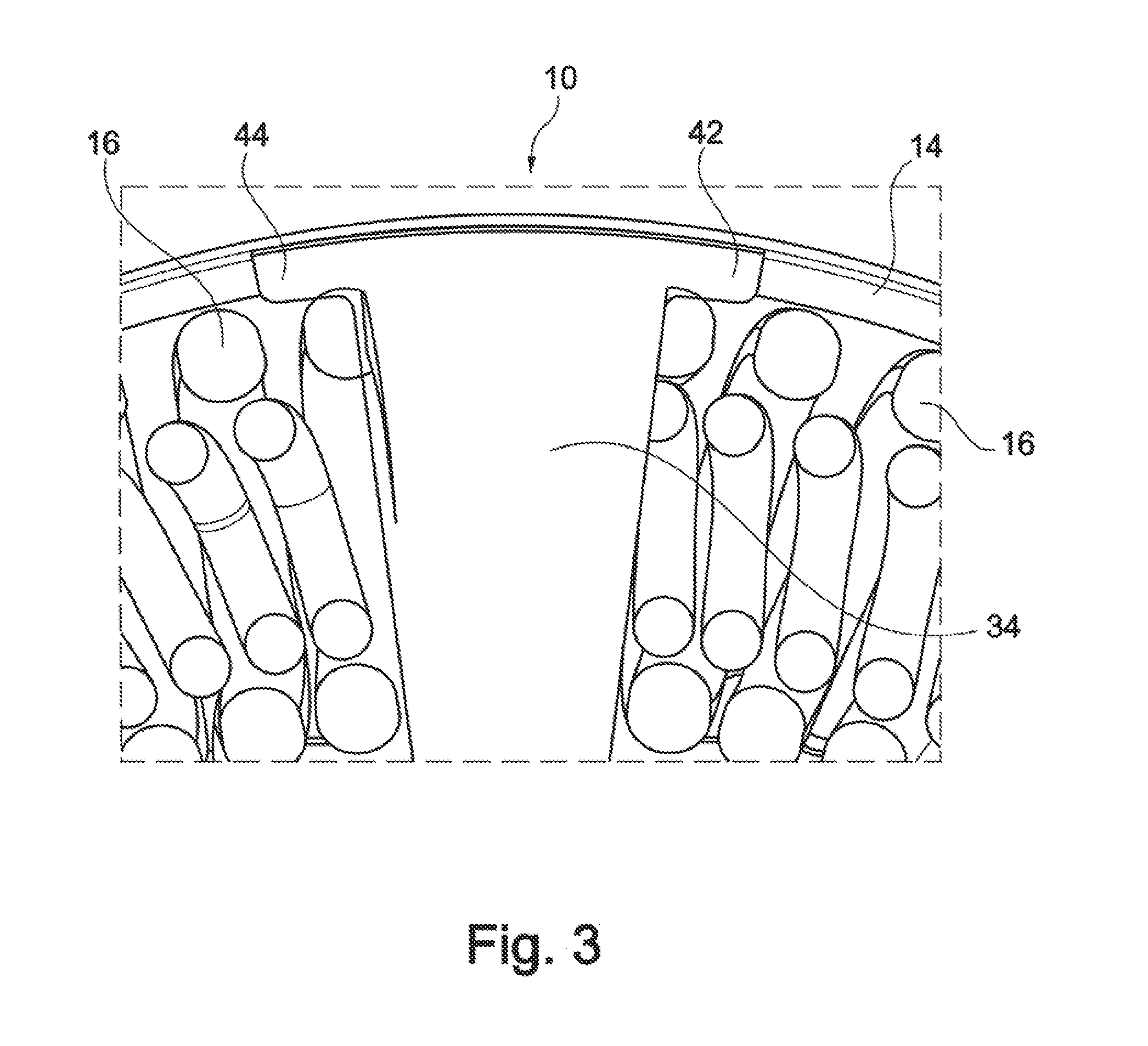
[0018]In FIG. 1, a torsional vibration damper 10 is represented in a perspective view in one embodiment of the invention. The torsional vibration damper 10, has a damper component 12 formed as a guide shell 14 in a radial external section.

[0019]Radially within the guide shell 14, two energy accumulator elements 16, 18 acting in parallel are nested in each other disposed in the form of coil springs, by which the radial outmost circumferential section is surrounded by the guide shell 14, so that the energy accumulator elements 16 of the guide shell 14 are fixed with respect to radial outward movement. The guide shell 14 thereby surrounds the radial extension of the energy accumulator elements 16 on at least one axial side and transforms into a plate-like section radially further inwards.

[0020]The damper component 12 formed as an input damper part 20 is connected non-rotatably with damper plate part 22 which is again connected non-rotatably with a plate carrier 24 of a clutch device. T...


PUM


Abstract

A torsional vibration damper with a damper component and a damper flange part limitedly rotatable within a circumferential clearance with respect to the damper component contrary to the effect of energy accumulator elements. The damper component is formed as a guide shell radially outside and surrounds the radial outmost circumferential section of the energy accumulator elements. The damper flange part comprises circumferentially disposed compression elements. The energy accumulator elements are circumferentially arranged in-between the compression elements. Cutouts formed in the guide shell and the compression elements engage radially into the cutouts whilst facilitating circumferential clearance.

Description

CROSS-REFERENCE TO RELATED APPLICATIONS[0001]This application claims priority from German Patent Application No. 10 2010 018 076.9, filed Apr. 22, 2010, which application is incorporated herein by reference in their entireties.FIELD OF THE INVENTION [0002]The invention relates to a torsional vibration damper.BACKGROUND OF THE INVENTION[0003]U.S. Pat. No. 5,964,328 A discloses a torsional vibration damper disposed within a hydrodynamic torque converter housing. The torsional vibration damper comprises a damper component and a damper flange part that, with respect to the damper component, is rotatable within circumferential clearance contrary to the effect of energy accumulator elements, for example, coil springs. The damper flange part is formed radially outside as a guide shell that surrounds the radially outmost circumferential section of the energy accumulator elements, and thus secures it against movement towards the outside. The damper flange part receives the energy accumulator...

Claims


Application Information

Patent Timeline
IPC IPC(8): F16F15/123
CPCF16F15/1232
Inventor DEGLER, MARIO
Owner SCHAEFFLER TECH AG & CO KG
Why Eureka
Try Eureka