Travel route estimation device and travel route estimation method used in the same device

Inactive Publication Date: 2011-10-27
TOYOTA JIDOSHA KK
View PDF55 Cites 21 Cited by
  • Summary
  • Abstract
  • Description
  • Claims
  • Application Information

AI Technical Summary

Benefits of technology

[0019]The first aspect allows to accurately estimate a shape of a travel route without increasing load of communication even when one's own-vehicle is traveling on a travel route without having any standstill objects installed, since a numerical value representing a shape of the travel route of the own-vehicle is estimated based on a displacement velocity of the own-vehicle over a travel route surface.
[0020]The second aspect allows to prevent a numerical value represented by information generated by a generation means from largely changing instantaneously, since a weighted average is obtained for numerical values representing shapes of two travel routes calculated by the filtering process means, and furthermore, weights are gradually increased or decreased based on each of the numerical values.
[0021]The third aspect allows to calculate and estimate the second numerical value, by selecting, in order to calculate the second numerical value based on the first numerical value, a filtering constant in advance based on the displacement velocity of the own-vehicle, and by condu

Problems solved by technology

However, with the first method, time is required for recognizing a behavior of the standstill object.
Therefore, with the first method, in cases such as when a change of the radius of curvature of the travel route of the own-vehicle is sharp, time is required for precisely estimating the

Method used


Image

  • Travel route estimation device and travel route estimation method used in the same device
  • Travel route estimation device and travel route estimation method used in the same device
  • Travel route estimation device and travel route estimation method used in the same device

Examples


first embodiment

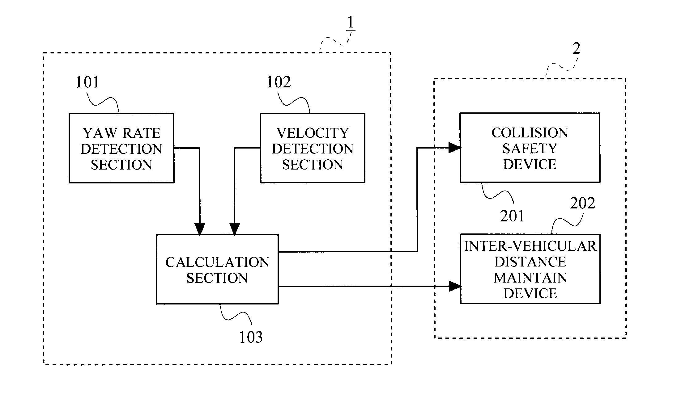
[0038]FIG. 1 is a block diagram showing an outlined configuration of a travel route estimation device 1 of a first embodiment of the present invention. The travel route estimation device 1 includes a yaw rate detection section 101, a velocity detection section 102, and a calculation section 103. In the descriptions of the present embodiment, a case where the travel route estimation device 1 is mounted on one's own-vehicle is described as one example.

[0039]Representatively, the yaw rate detection section 101 is a sensor such as a gyro sensor which can detect an angle of rotation; and when the own-vehicle is rotated about an axis that passes through the center of gravity of the own-vehicle in the vertical direction, the yaw rate detection section 101 successively detects, as a rotational angular velocity (yaw rate), a displacement velocity of an angle of rotation (yaw angle) toward a rotation direction among directions over a travel route surface of the own-vehicle. Every time the rot...

second embodiment

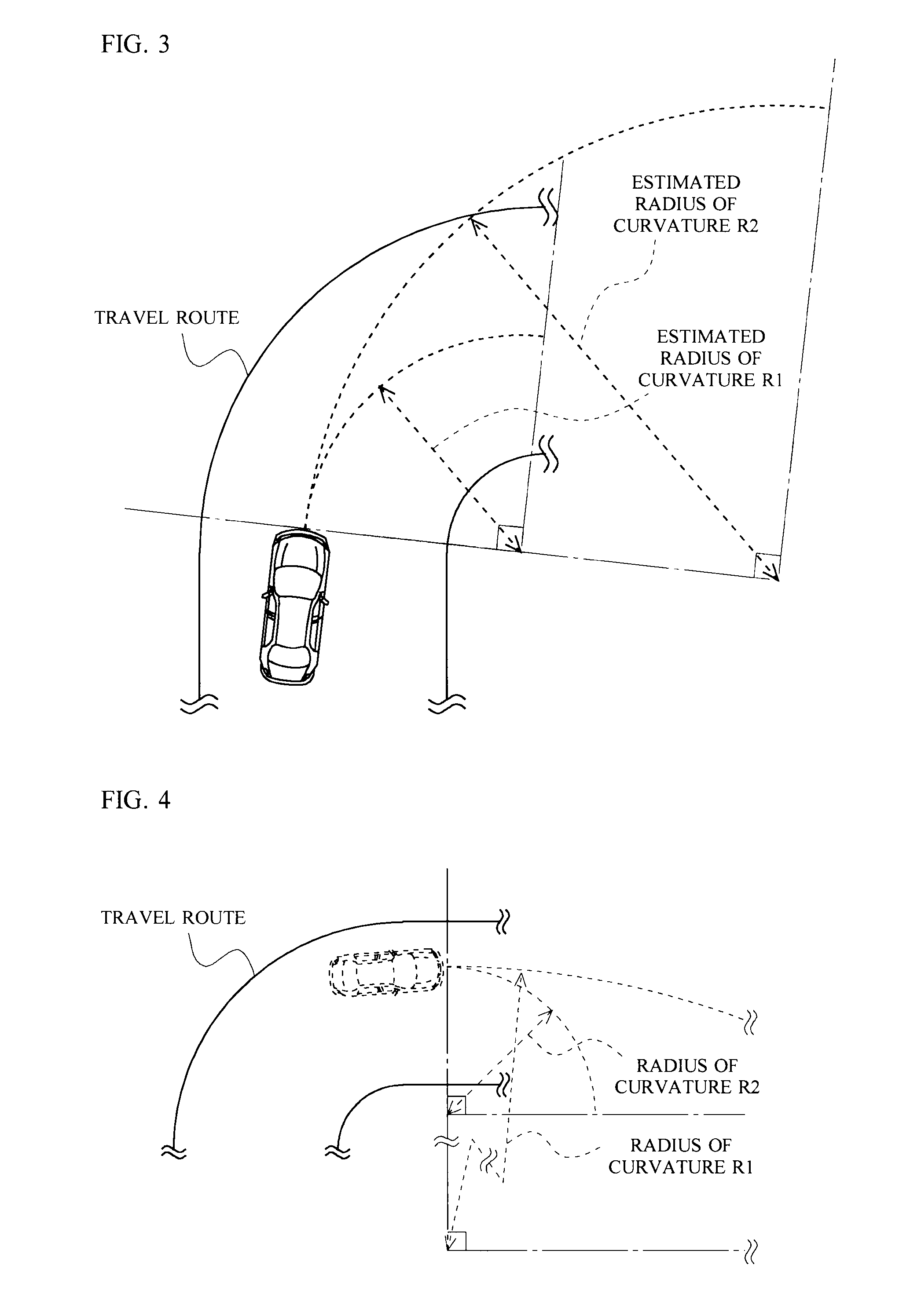
[0106]In the first embodiment, the calculation section 103 has been described to calculate the estimated radius-of-curvature KR which is a weighted average, while conducting both the filtering process for calculating the estimated radius-of-curvature R1 and the filtering process for calculating the estimated radius-of-curvature R2. However, in the present invention, depending on the type of the travel route in which the own-vehicle is traveling, a filtering constant used in the filtering processes for calculating an estimated radius-of-curvature can be determined from among either one of the estimated radius-of-curvature R1 and estimated radius-of-curvature R2 described in the first embodiment, and then, an estimated radius-of-curvature calculated in a filtering process using the determined filtering constant may be defined as the estimated radius-of-curvature KR described in the first embodiment.

[0107]In more detail, the calculation section 103 stores, in the storage section which ...


PUM


Abstract

Provided is a travel route estimation device capable of accurately estimating, without excessively increasing communication load of the device, a shape of a travel route even when one's own-vehicle is traveling on a travel route that does not have any objects installed on the route. A calculation section calculates and successively stores a radius of curvature of the travel route based on a yaw rate detected by a yaw rate detection section and on a traveling velocity detected by a velocity detection section. When conducting a filtering process for reducing variation of the calculate radius of curvature, the calculation section selects a filtering constant for multiplying the stored radius of curvature in accordance with the type of the travel route of the own-vehicle, and generates information representing a radius of curvature obtained by conducting at least one filtering process by using the selected filtering constant.

Description

TECHNICAL FIELD[0001]The present invention relates to a travel route estimation device, and more specifically, relates to a travel route estimation device mounted on a movable body such as an automobile.BACKGROUND ART[0002]In recent years, in order to conduct an inter-vehicular distance maintenance control and the like, a device that estimates a radius of curvature of a travel route of one's own vehicle is mounted on a vehicle. As methods for estimating the radius of curvature of the travel route of the own-vehicle, there are two methods which will be described next.[0003]A first method is a method that estimates the radius of curvature of the travel route of the own-vehicle based on such as a relative position and a relative velocity, which are measured by a distance / angle measuring instrument mounted on the own-vehicle, of a standstill object (for example, an object installed on the route such as a reflector) existing on the travel route of the own-vehicle. With the first method, ...

Claims


Application Information

Patent Timeline
IPC IPC(8): G06F7/00B60W40/06
CPCB60W30/0953B60W40/072B60W40/076B60W2520/14B60W2050/0052B60W2520/10B60W2050/0051
Inventor TSUNEKAWA, JUN
Owner TOYOTA JIDOSHA KK
Why Eureka
Try Eureka